0%

gcc 和 GCC 是两个不同的东西。

GCC:GNU Compiler Collection(GUN 编译器集合),它可以编译C、C++、JAV、Fortran、Pascal、Object-C、Ada等语言。

gcc:GCC中的GUN C Compiler(C 编译器)

g++:GCC中的GUN C++ Compiler(C++编译器)

一个有趣的事实就是,就本质而言,gcc和g++并不是编译器,也不是编译器的集合,它们只是一种驱动器,根据参数中要编译的文件的类型,调用对应的GUN编译器而已,比如,用gcc编译一个c文件的话,会有以下几个步骤:

Step1:Call a preprocessor, like cpp.

Step2:Call an actual compiler, like cc or cc1.

Step3:Call an assembler, like as.

Step4:Call a linker, like ld

由于编译器是可以更换的,所以gcc不仅仅可以编译C文件

所以,更准确的说法是:gcc调用了C compiler,而g++调用了C++ compiler

gcc和g++的主要区别

  1. 对于 .c和.cpp文件,gcc分别当做c和cpp文件编译(c和cpp的语法强度是不一样的)

  2. 对于 .c和.cpp文件,g++则统一当做cpp文件编译

  3. 使用g++编译文件时,g++会自动链接标准库STL,而gcc不会自动链接STL

  4. gcc在编译C文件时,可使用的预定义宏是比较少的

  5. gcc在编译cpp文件时/g++在编译c文件和cpp文件时(这时候gcc和g++调用的都是cpp文件的编译器),会加入一些额外的宏,这些宏如下:

1
2
3
4
5
6
#define __GXX_WEAK__ 1
#define __cplusplus 1
#define __DEPRECATED 1
#define __GNUG__ 4
#define __EXCEPTIONS 1
#define __private_extern__ extern
  1. 在用gcc编译c++文件时,为了能够使用STL,需要加参数 –lstdc++ ,但这并不代表 gcc –lstdc++ 和 g++等价,它们的区别不仅仅是这个

其主要参数:

-g - turn on debugging (so GDB gives morefriendly output)

-Wall - turns on most warnings

-O or -O2 - turn on optimizations

-o - name of the output file

-c - output an object file (.o)

-I - specify an includedirectory

-L - specify a libdirectory

-l - link with librarylib.a

使用示例:g++ -ohelloworld -I/homes/me/randomplace/include helloworld.C

介绍

作为一个日常开发的程序员,三大平台都在日常使用的软件(生产力工具及娱乐工具)如下:

  • utools
  • typora
  • visual studio code
  • picgo
  • sogou pinyin
  • snipaste(win) / flameshot(linux) / ishot(mac)
  • cosbrowser
  • nodejs 及 npm
  • hexo
  • qqmusic

win和mac安装软件都相对简单,linux安装需要使用者自身具有一定的耐心和排除困难的经验,为了更好地体验linux的方便,这里对linux装机后的生产力工具安装做个简单记录,以下安装均在 KALI (Kali也属于Debian系Linux)上进行。

使用Linux系统的最大好处是 “一个终端即可解决即可开启大部分软件和解决日常事务,最多再开启一个utools”。

Linux上的软件安装方式通常分为四种方式:

  • 通过 dpkg 命令安装 .deb 文件
  • 通过 apt 或其他软件的软件安装命令(如,npmpip)来安装
  • 通过 ln 链接将程序绑定至全局变量来 “安装” 和使用
  • 通过直接调用 AppImage 的方式直接使用软件,此类方式需要一般需要手动双击执行

其中前三种方式的困难因系统而异,所说的困难是可能出现所安装的软件依赖不存在,需要使用者自行去定位(包括下载和添加源)和安装,或者链接方式错误等。而Linux源众多,每个节点的速度及其更新情况都不太一样,需要使用者判断。

uTools & Flameshot

uTools 使用的是 .deb 安装包安装,flameshot 使用 apt 命令进行安装。

依赖文件

  1. libspdlog1-fmt7 是 flameshot所需文件
  2. libappindicator3-1 是 utools所需文件

libspdlog1

尝试安装utools和flameshot后,apt会提示缺少文件。使用 sudo apt-get install libspdlog1-fmt7 来安装 libspdlog1-fmt7

如果触发安装破损修复,使用apt --fix-broken install 可以让apt自动修复安装错误,自动补全依赖文件。

libappindicator3

libappindicator3-1 文件需要使用者往 /etc/apt/source.list 中添加debian源,需要使用者掌握基本的 vim 软件使用方法(包括插入、保存和退出)。

  • 使用 sudo vim /etc/apt/sources.list 命令打开 source.list

  • i 进入 插入模式,复制粘贴 deb http://ftp.de.debian.org/debian sid main 至空白处,按 ESC 键,再依次输入 :wq 进行保存和退出。

  • 在终端输入 sudo apt-get update 进行源库软件列表更新,再次尝试 sudo apt-get install libappindicator3 来安装

    libappindicator3-1 and libappindicator3-7

最后再次尝试以下两条语句即可成功安装 utools 和 flameshot 。

1
2
sudo dpkg -i utools_1.3.5_amd64.deb
sudo apt-get install flameshot

Typora

TYPORA.IO 官方提供的安装代码如下:

1
2
3
4
sudo apt-key adv --keyserver keyserver.ubuntu.com --recv-keys BA300B7755AFCFAE
sudo add-apt-repository 'deb https://typora.io/linux ./'
sudo apt-get update
sudo apt-get install typora

其中,向apt中添加源的第二条语句 add-apt-repository 会因缺乏 PPA 而无法执行,可以参考 sudo: add-apt-repository:找不到命令的解决方法 进行安装。

也可以参考 libappindicator3 的源添加方法,往 source.list 文件中添加 deb https://typora.io/linux ./ 来添加源。

添加成功后即可成功安装tyopra。

Sogou Pinyin

从搜狗官方下载的 Sogou 安装包,需要用 sudo dpkg -i sogoupinyin_2.4.0.3469_amd64.deb 命令进行安装,会遇到以下缺乏库的提示,主要是因为缺少 fcitx 的提示。

1
2
3
4
5
6
7
8
9
10
11
12
13
14
15
16
17
18
19
20
21
22
23
24
25
26
27
28
29
30
dpkg: 依赖关系问题使得 sogoupinyin 的配置工作不能继续:
sogoupinyin 依赖于 fcitx (>= 1:4.2.8);然而:
未安装软件包 fcitx
sogoupinyin 依赖于 fcitx-frontend-gtk2;然而:
未安装软件包 fcitx-frontend-gtk2。
sogoupinyin 依赖于 fcitx-frontend-gtk3;然而:
未安装软件包 fcitx-frontend-gtk3。
sogoupinyin 依赖于 fcitx-frontend-qt5;然而:
未安装软件包 fcitx-frontend-qt5。
sogoupinyin 依赖于 fcitx-module-kimpanel;然而:
未安装软件包 fcitx-module-kimpanel。
sogoupinyin 依赖于 fcitx-module-x11;然而:
未安装软件包 fcitx-module-x11。
sogoupinyin 依赖于 im-config;然而:
未安装软件包 im-config。
sogoupinyin 依赖于 fcitx-libs | libfcitx-config4;然而:
未安装软件包 fcitx-libs。
未安装软件包 libfcitx-config4。
sogoupinyin 依赖于 fcitx-libs | libfcitx-qt0;然而:
未安装软件包 fcitx-libs。
未安装软件包 libfcitx-qt0。
sogoupinyin 依赖于 fcitx-libs | libfcitx-utils0;然而:
未安装软件包 fcitx-libs。
未安装软件包 libfcitx-utils0。
sogoupinyin 依赖于 fcitx-ui-classic;然而:
未安装软件包 fcitx-ui-classic。
sogoupinyin 依赖于 libqt5quickwidgets5;然而:
未安装软件包 libqt5quickwidgets5。
sogoupinyin 依赖于 qml-module-qtquick2;然而:
未安装软件包 qml-module-qtquick2。

Fcitx[ˈfaɪtɪks]是 (Free Chinese Input Toy for X) 的英文缩写,中文名为小企鹅输入法,是一个以 GPL 方式发布的输入法框架, 编写它的目是为桌面环境提供一个灵活的输入方案,彻底解决在GNU/Linux下没有一个好的中文输入法的问题。

FCITX

通过输入 sudo apt-get install fcitx 来尝试安装,会触发 apt fix broken install, 此时只要再次输入 sudo apt --fix-broken install 来修复。

1
2
3
4
5
6
7
8
9
10
11
12
13
14
15
16
17
18
19
20
21
22
23
24
25
26
27
下列软件包有未满足的依赖关系:
fcitx : 依赖: fcitx-bin 但是它将不会被安装
依赖: fcitx-data 但是它将不会被安装
依赖: fcitx-modules 但是它将不会被安装
推荐: fcitx-config-gtk 但是它将不会被安装 或
kde-config-fcitx 但是它将不会被安装
推荐: fcitx-frontend-all 但是它将不会被安装 或
fcitx-frontend-fbterm 但是它将不会被安装
推荐: fcitx-ui-classic 但是它将不会被安装 或
fcitx-ui-light 但是它将不会被安装
推荐: im-config (>= 0.5) 但是它将不会被安装
sogoupinyin : 依赖: fcitx-frontend-gtk2 但是它将不会被安装
依赖: fcitx-frontend-gtk3 但是它将不会被安装
依赖: fcitx-frontend-qt5 但是它将不会被安装
依赖: fcitx-module-kimpanel 但是它将不会被安装
依赖: fcitx-module-x11 但是它将不会被安装
依赖: im-config 但是它将不会被安装
依赖: fcitx-libs 但是它将不会被安装 或
libfcitx-config4 但是它将不会被安装
依赖: fcitx-libs 但是它将不会被安装 或
libfcitx-qt0 但无法安装它
依赖: fcitx-libs 但是它将不会被安装 或
libfcitx-utils0 但是它将不会被安装
依赖: fcitx-ui-classic 但是它将不会被安装
依赖: libqt5quickwidgets5 但是它将不会被安装
依赖: qml-module-qtquick2 但是它将不会被安装
E: 有未能满足的依赖关系。请尝试不指明软件包的名字来运行“apt --fix-broken install”(也可以指定一个解决办法)。

安装成功

FIX-BROKEN 成功后,再次尝试安装 FCITX 就可以提示成功;接着安装sogou即可。

1
2
3
4
5
6
7
8
9
10
11
12
13
14
15
16
$ sudo apt-get install fcitx                   
正在读取软件包列表... 完成
正在分析软件包的依赖关系树... 完成
正在读取状态信息... 完成
fcitx 已经是最新版 (1:4.2.9.8-3)。
fcitx 已设置为手动安装。
升级了 0 个软件包,新安装了 0 个软件包,要卸载 0 个软件包,有 136 个软件包未被升级。

$ sudo dpkg -i sogoupinyin_2.4.0.3469_amd64.deb
(正在读取数据库 ... 系统当前共安装有 270000 个文件和目录。)
准备解压 sogoupinyin_2.4.0.3469_amd64.deb ...
正在解压 sogoupinyin (2.4.0.3469) 并覆盖 (2.4.0.3469) ...
正在设置 sogoupinyin (2.4.0.3469) ...
正在处理用于 mailcap (3.69) 的触发器 ...
正在处理用于 desktop-file-utils (0.26-1) 的触发器 ...
正在处理用于 hicolor-icon-theme (0.17-2) 的触发器 ...

依赖库

sogou输入法依赖库具体如下:

1
2
3
4
5
6
7
8
9
10
下列【新】软件包将被安装:
dbus-x11 fcitx fcitx-bin fcitx-config-common fcitx-config-gtk fcitx-data
fcitx-frontend-all fcitx-frontend-gtk2 fcitx-frontend-gtk3
fcitx-frontend-qt5 fcitx-libs fcitx-module-dbus fcitx-module-kimpanel
fcitx-module-lua fcitx-module-x11 fcitx-modules fcitx-ui-classic
fcitx5-module-quickphrase-editor im-config libfcitx-config4
libfcitx-core0 libfcitx-gclient1 libfcitx-qt5-1 libfcitx-qt5-data
libfcitx-utils0 libgettextpo0 libpresage-data libpresage1v5
libqt5qmlworkerscript5 libqt5quickwidgets5 libtinyxml2.6.2v5 presage
qml-module-qtquick2

NodeJS & Hexo

使用 sudo apt-get install nodejssudo apt-get install node.js 均可以实现node.js 的安装,但是只能安装V12版。

可以在官方下载 node-v16.2.0-linux-x64.tar.xz ,并使用以下命令进行解压:

1
2
xz -d node-v16.2.0-linux-x64.tar.xz
tar -xvf node-v16.2.0-linux-x64.tar

解压完毕之后,以管理员身份将该文件移动至 /usr/local/node ,以下命令将 node-v16.2.0-linux-x64 拷贝的同时进行了 重命名 操作。

1
sudo mv /home/XXX/downloads/node-v16.2.0-linux-x64 /usr/local/node

注:XXX是用户名

然后进行软连接:

1
2
sudo ln -s /usr/local/node/bin/node /usr/local/bin
sudo ln -s /usr/local/node/bin/npm /usr/local/bin

Linux ln(英文全拼:link files)命令是一个非常重要命令,它的功能是为某一个文件在另外一个位置建立一个同步的链接。

当我们需要在不同的目录,用到相同的文件时,我们不需要在每一个需要的目录下都放一个必须相同的文件,我们只要在某个固定的目录,放上该文件,然后在 其它的目录下用ln命令链接(link)它就可以,不必重复的占用磁盘空间。

以上是 ln 链接命令的解释,实际最重要的作用是将某个已下载的软件及其命令定义至全局,在终端的任意一个目录位置都可以使用该软件。

“安装” 成功

实际上新版的nodejs并不涉及 前述 dpkgapt 命令的安装,但软连接该文件目录至 /usr/local/bin 后,能实现安装效果,使用 node -vnpm -v 命令即可进行测试。

1
2
3
4
5
$ node -v
v16.2.0

$ npm -v
7.14.0

其他

对于使用此类安装方式进行安装的 依赖于nodejs的应用如果需要在全局进行使用可能也需要进行软连接,如 hexo。

使用 npm install hexo-cli -g 成功安装hexo后提示如下:

1
2
$ whereis hexo
hexo:

此时需要将 /usr/local/node/bin 文件夹下安装的程序也拉到全局变量中 /usr/local/bin 中。再次使用 whereis 命令检测时即可成功。

1
2
3
4
$ sudo ln -s /usr/local/node/bin/hexo /usr/local/bin/hexo

$ whereis hexo
hexo: /usr/local/bin/hexo

Visual Studio Code

VS code安装使用 dpkg 命令,最大的问题是微软的源下载太慢,以下提供个人下载点,安装过程不再记录。

个人下载点: Visual Studio Code Linux (deb)

PicGo

Typora_Picgo 有 command-line 版 和 app 版,参考 PicGo官方文档 (GFW封锁了github.io域名后缀,需要梯子)进行安装吧。

QQmusic & cosbrowser

这两个软件都是腾讯家产品,下载、安装和使用都很方便。

其中,QQMusic使用 dpkg 命令进行安装即可, cosbrowserAppImage 格式文件,直接打开即可使用,无需安装。

彩蛋sudo apt-get install cmatrix

---EOF---

barrgroup.com

One of the least used but potentially most useful features of the C preprocessor is the ANSI-specified #error directive. Here's a look at a couple of clever uses for #error that have proven invaluable in embedded software development.

The syntax of #error is very straightforward:

1
#error <writer supplied error message>  //开发者提供的错误信息

<writer supplied error message> 中可包含任何可显示的文本,甚至不需要使用双引号 ""

The <writer supplied error message> can consist of any printable text. You don't even have to enclose the text in quotes. (Technically, the message is optional--though it rarely makes sense to omit it.)

当C预处理器遇到 #error 语句时,会将停止编译,并将错误信息输出至 stderr 文件。C编译器的典型错误信息如下:

When the C preprocessor encounters a #error statement, it causes compilation to terminate and the writer-supplied error message to be printed to stderr (link is external). A typical error message from a C compiler looks like this:

1
2
Filename(line_number): Error! 
Ennnn: <writer supplied error message>

where Filename is the source file name, line_number is the line number where the #error statement is located, and Ennnn is a compiler-specific error number. Thus, the #error message is basically indistinguishable from ordinary compiler error messages.

"Wait a minute," you might say. "I spend enough time trying to get code to compile and now he wants me to do something that causes more compiler errors?" Absolutely! The essential point is that code that compiles but is incorrect is worse than useless. I've found three general areas in which this problem can arise and #error can help. Read on and see if you agree with me.

Incomplete code

I tend to code using a step-wise refinement approach, so it isn't unusual during development for me to have functions that do nothing, for loops that lack a body, and so forth. Consequently, I often have files that are compilable but lack some essential functionality. Working this way is fine, until I'm pulled off to work on something else (an occupational hazard of being in the consulting business). Because these distractions can occasionally run into weeks, I sometimes return to the job with my memory a little hazy about what I haven't completed. In the worst-case scenario (which has occurred), I perform a make, which runs happily, and then I attempt to use the code. The program, of course, crashes and burns, and I'm left wondering where to start.

In the past, I'd comment the file to note what had been done and what was still needed. However, I found this approach to be rather weak because I then had to read all my comments (and I comment heavily) in order to find what I was looking for. Now I simply enter something like the following in an appropriate place in the file:

1
#error *** Nigel - Function incomplete. Fix before using *** 

Thus, if I forget that I haven't done the necessary work, an inadvertent attempt to use the file will result in just about the most meaningful compiler message I'll ever receive. Furthermore, it saves me from having to wade through pages of comments, trying to find what work I haven't finished.

Compiler-dependent code

As much as I strive to write portable code, I often find myself having to trade off performance for portability - and in the embedded world, performance tends to win. However, what happens if a few years later I reuse some code without remembering that the code has compiler-specific peculiarities? The result is a much longer debug session than is necessary. But a judicious #error statement can prevent a lot of grief. A couple of examples may help.

Example 1

Some floating-point code requires at least 12 digits of resolution to return the correct results. Accordingly, the various variables are defined as type long double. But ISO C only requires that a long double have 10 digits of resolution. Thus on certain machines, a long double may be inadequate to do the job. To protect against this, I would include the following:

1
2
3
4
5
#include <float.h>
#if (LDBL_DIG < 12)
#error *** long doubles need 12 digit resolution.
Do not use this compiler! ***
#endif

This approach works by examining the value of an ANSI-mandated constant found in float.h (link is external).

Example 2

An amazing amount of code makes invalid assumptions about the underlying size of the various integer types. If you have code that has to use an int (as opposed to a user-specified data type such as int16), and the code assumes that an int is 16 bits, you can do the following:

1
2
3
4
5
#include <limits.h>
#if (INT_MAX != 32767)
#error *** This file only works with 16-bit int.
Do not use this compiler! ***
#endif

Again, this works by checking the value of an ANSI-mandated constant. This time the constant is found in the file limits.h (link is external). This approach is a lot more useful than putting these limitations inside a big comment that someone may or may not read. After all, you have to read the compiler error messages.

Conditionally-compiled code

Since conditionally compiled code seems to be a necessary evil in embedded programming, it's common to find code sequences such as the following:

1
2
3
4
5
#if defined OPT_1 
/* Do option_1 */
#else
/* Do option_2 */
#endif

As it is written, this code means the following: if and only if OPT_1 is defined, we will do option_1; otherwise we'll do option_2. The problem with this code is that a user of the code doesn't know (without explicitly examining the code) that OPT_1 is a valid compiler switch. Instead, the naive user will simply compile the code without defining OPT_1 and get the alternate implementation, irrespective of whether that is what's required or not. A more considerate coder might be aware of this problem, and instead do the following:

1
2
3
4
5
#if defined OPT_1 
/* Do option 1 */
#elif defined OPT_2
/* Do option 2*/
#endif

In this case, failure to define either OPT_1 or OPT_2 will typically result in an obscure compiler error at a point later in the code. The user of this code will then be stuck with trying to work out what must be done to get the module to compile. This is where #error comes in. Consider the following code sequence:

1
2
3
4
5
6
7
#if defined OPT_1 
/* Do option_1 */
#elif defined OPT_2
/* Do option_2 */
#else
#error *** You must define one of OPT_1 or OPT_2 ***
#endif

Now the compilation fails, but at least it tells the user explicitly what to do to make the module compile. I know that if this procedure had been adopted universally, I would have saved a lot of time over the years trying to reuse other people's code.

So there you have it. Now tell me, don't you agree that #error is a really useful part of the preprocessor, worthy of your frequent use-and occasional praise?

geeksforgeeks.org

NPM (Node Package Manager) is the default package manager employed in JavaScript runtime environment in Node.js. It has a very frequently used command npm install [Package Name] –save. But the fact is there is no difference between npm install [Package Name] and npm install [Package Name] –save in the later version after npm 5.0.0 onwards.

Before npm 5.0.0, it was necessary to add --save after package name because it will save the installed package to package.json file in the dependency section. If you are using a recent version of npm save yourself from unnecessary typing and use npm install [Package Name] instead of npm install [Package Name] --save by default it will add the installed package to the dependency list in the package.json file.

NPM has several commands which are listed below:

  1. –save or -S:

    When the following command is used with npm install this will save all your installed core packages into the dependency section in the package.json file. Core dependencies are those packages without which your application will not give desired results. But as mentioned earlier, it is an unnecessary feature in the npm 5.0.0 version onwards.

    1
    npm install --save
  2. –save-prod or -P:

    The following command is introduced in the later version of npm it will perform the same task as the

    1
    --save

    command unless any other command such as

    1
    -D

    or

    1
    -O

    is present.

    1
    npm install --save-prod
  3. –save-dev or -D:

    With

    1
    --save-dev

    or

    1
    -D

    command your installed packages will be added to devDependency section of the package.json file. Development dependencies are those packages which only meant for development purpose it will not affect the application’s result.

    1
    npm install --save-dev
  4. –save-optional or -O:

    When this command is used the install the that packages will be listed under the optional Dependency section of the package.json file. Optional dependencies are those packages which are only used when a particular feature of the application is used and will not be required if that functionality isn’t used.

    1
    npm install --save-optional
  5. –no-save:

    When this command is used with npm install it will not allow the installed packages from being saved into the dependency section.

    1
    npm install --no-save

Note: NPM provides two additional options to save dependencies into package.json file.

  1. –save-exact or -E:

    This is an additional or optional command provided by the npm that will save the exact version of the installed packages which are configured at the time of development. It will not download the dependencies from npm’s default server range operator.

    1
    npm install --save-exact
  2. –save-bundle or -B:

    The following command is also an optional command when

    1
    --save-bundle

    or

    1
    -B

    is used. This will also add the saved dependencies under the bundleDependency list.

    1
    npm install --save-bundle

cnblogs.com

对齐定义

内存地址对齐,是一种在计算机内存中排列数据、访问数据的一种方式。

对齐分类

内存地址对齐包含了两种相互独立又相互关联的部分:基本数据对齐结构体数据对齐

当今的计算机在计算机内存中读写数据时都是 按字(word)大小块来进行操作 的。在32位系统中,数据总线宽度为32位,每次能读取4bytes,地址总线宽度为32,因此最大的寻址空间为232bits=4GB,但是最低2位A[0]、A[1]是不用于寻址,A[2-31]才能存储器相连,因此只能访问4的倍数地址空间,但是总的寻址空间还是230bits字长=4GB,因此在 内存中所有存放的基本类型数据的首地址的最低两位都是0,除结构体中的成员变量

基本类型数据对齐就是数据在内存中的 偏移地址必须等于一个字的倍数,按这种存储数据的方式,可以提升系统在读取数据时的性能。为了对齐数据,可能必须在上一个数据结束和下一个数据开始的地方插入一些没有用处字节,这就是结构体数据对齐

基本数据对齐示例

例如,假设计算机的字大小为4bytes,因此变量在内存中的首地址都是满足4地址对齐,CPU只能对4的倍数的地址进行读取,而每次能读取4个字节大小的数据。

假设有一个整型的数据a的首地址不是4的倍数(如下图所示),不妨设为 0X00FFFFF3,则该整型数据存储在地址范围为0X00FFFFF3 ~0X00FFFFF6的存储空间中,而CPU每次只能对4的倍数内存地址进行读取,因此想读取a的数据,CPU要分别在 0X00FFFFF00X00FFFFF4 进行两次内存读取,而且还要对两次读取的数据进行处理才能得到a的数据,而一个程序的瓶颈往往不是CPU的速度,而是取决于内存的带宽,因为CPU得处理速度要远大于从内存中读取数据的速度,因此减少对内存空间的访问是提高程序性能的关键。从上例可以看出,采取内存地址对齐策略是提高程序性能的关键。

也就是说,不对齐内存地址的话会造成CPU对内存中数据访问范围的增大,造成性能浪费。

结构体对齐示例

首先我们先看看下面的C语言的结构体:

1
2
3
4
5
6
typedef struct MemAlign
{
int a;
char b[3];
int c;
}MemAlign;

以上这个结构体占用内存多少空间呢?

也许你会说,这个简单,计算每个类型的大小,将它们相加就行了,以32bit平台为例,int类型占4bytes,char占用1byte,所以:4 + 3 + 4 = 11bytes,那么这个结构体一共占用11字节空间。

实际上用sizeof运算符来求出这个结构体占用内存空间大小,sizeof(MemAlign),出乎意料的是,结果居然为12?

是因为这个结构体被优化了,这个优化有个另外一个名字叫“对齐”,那么这个对齐到底做了什么样的优化呢。

img

相信学过汇编的朋友都很熟悉这张图,这张图就是CPU与内存如何进行数据交换的模型,其中,左边蓝色的方框是CPU,右边绿色的方框是内存,内存上面的0~3是内存地址。

上图以32位CPU作为代表,32位CPU是以双字(DWORD)为单位进行数据传输的,因此 在32位系统中,无论是8位、16位还是32位都是以双字进行数据传输

非32位数据非对齐传输示例

8位或16位一样可以传输,但是事情并非像我们想象的那么简单。

一个int类型4字节的数据如果放在上图内存地址1开始的位置,那么这个数据占用的内存地址为1~4,那么这个数据就被分为了2个部分,一个部分在地址0~3中,另外一部分在地址4~7中,又由于32位CPU以双字进行传输,所以,CPU会分2次进行读取,一次先读取地址0~3中内容,再一次读取地址4~7中数据,最后CPU提取并组合出正确的int类型数据,舍弃掉无关数据。那么反过来,如果我们把这个int类型4字节的数据放在上图从地址0开始的位置会怎样呢?读到这里,也许你明白了,CPU只要进行一次读取就可以得到这个int类型数据了。没错,就是这样,这次CPU只用了一个周期就得到了数据,由此可见,对内存数据的摆放是多么重要啊,摆放正确位置可以减少CPU的使用资源

对齐原则

  • 第一个成员的首地址为0

  • 每个成员的首地址是自身大小的整数倍

    • 以4bytes对齐为例,如果自身大小大于4bytes,都以4bytes整数倍为基准对齐。
  • 最后以结构总体对齐。

    • 以4字节bytes为例,取结构体中最大成员类型倍数,如果超过4字节,都以4字节整数倍为基准对齐。(其中这一条还有个名字叫:“补齐”,补齐的目的就是多个结构变量挨着摆放的时候也满足对齐的要求。)

基本数据对齐与结构补齐示例

上述的三原则听起来还是比较抽象,那么接下来我们通过一个例子来加深对内存对齐概念的理解,下面是一个结构体,我们动手算出下面结构体一共占用多少内存?假设我们以32位平台并且以4字节对齐方式:

1
2
3
4
5
6
7
8
9
#pragma pack(4)
typedef struct MemAlign
{
char a[18];
double b;
char c;
int d;
short e;
}MemAlign;

下图为对齐后结构如下:

img

我们就以这个图来讲解是如何对齐的:

第一个成员(char a[18]):首先,假设我们把它放到内存开始地址为0的位置,由于第一个成员占18个字节,所以第一个成员占用内存地址范围为0~18。

第二个成员(double b):由于double类型占8字节,又因为8字节大于4字节,所以就以4字节对齐为基准。由于第一个成员结束地址为18,那么地址18并不是4的整数倍,我们需要再加2个字节,也就是从地址20开始摆放第二个成员。

第三个成员(char c):由于char类型占1字节,任意地址是1字节的整数倍,所以我们就直接将其摆放到紧接第二个成员之后即可。

第四个成员(int d):由于int类型占4字节,但是地址29并不是4的整数倍,所以我们需要再加3个字节,也就是从地址32开始摆放这个成员。

第五个成员(short e):由于short类型占2字节,地址36正好是2的整数倍,这样我们就可以直接摆放,无需填充字节,紧跟其后即可。

这样我们内存对齐就完成了。但是离成功还差那么一步,那是什么呢?对,是对整个结构体补齐,接下来我们就补齐整个结构体。那么,先让我们回顾一下补齐的原则:“以4字节对齐为例,取结构体中最大成员类型倍数,如果超过4字节,都以4字节整数倍为基准对齐。”在这个结构体中最大类型为double类型(占8字节),又由于8字节大于4字 节,所以我们还是以4字节补齐为基准,整个结构体结束地址为38,而地址38并不是4的整数倍,所以我们还需要加额外2个字节来填充结构体,如下图红色的就是补齐出来的空间:

img

到此为止,我们内存对齐与补齐就完毕了!接下来我们用实验来证明真理,程序如下:

复制代码
1
2
3
4
5
6
7
8
9
10
11
12
13
14
15
16
17
18
19
20
21
22
23
24
25
26
27
28
29
30
31
32
33
34
35
36
37
#include <stdio.h>
#include <memory.h>

// 由于VS2010默认是8字节对齐,我们
// 通过预编译来通知编译器我们以4字节对齐
#pragma pack(4)

// 用于测试的结构体
typedef struct MemAlign
{
char a[18]; // 18 bytes
double b; // 08 bytes
char c; // 01 bytes
int d; // 04 bytes
short e; // 02 bytes
}MemAlign;

int main()
{
// 定义一个结构体变量
MemAlign m;
// 定义个以指向结构体指针
MemAlign *p = &m;
// 依次对各个成员进行填充,这样我们可以
// 动态观察内存变化情况
memset( &m.a, 0x11, sizeof(m.a) );
memset( &m.b, 0x22, sizeof(m.b) );
memset( &m.c, 0x33, sizeof(m.c) );
memset( &m.d, 0x44, sizeof(m.d) );
memset( &m.e, 0x55, sizeof(m.e) );
// 由于有补齐原因,所以我们需要对整个
// 结构体进行填充,补齐对齐剩下的字节
// 以便我们可以观察到变化
memset( &m, 0x66, sizeof(m) );
// 输出结构体大小
printf( "sizeof(MemAlign) = %d", sizeof(m) );
}
复制代码

程序运行过程中,查看内存如下:

img

其中,各种颜色带下划线的代表各个成员变量,蓝色方框的代表为内存对齐时候填补的多余字节,由于这里看不到补齐效果,我们接下来看下图,下图篮框包围的字节就是与上图的交集以外的部分就是补齐所填充的字节。

img

在最后,我在谈一谈关于补齐的作用,补齐其实就是为了让这个结构体定义的数组变量时候,数组内部,也同样满足内存对齐的要求,为了更好的理解这点,我做了一个跟本例子相对照的图:

img

参考链接

https://blog.csdn.net/donkeylong/article/details/4909720

https://blog.csdn.net/cyousui/article/details/17655051

X86指令集介绍

X86指令集的基本特色

  • 向下兼容
  • 变长指令
    • 1-15字节,多为2-3字节长度
  • 多种寻址方式(可访问不对齐内存地址)
image-20210517203416861

X86寄存器

指令集的通用寄存器个数有限

X86-32下指令集通用寄存器数量为8个,x86-64下为16个

至多只有一个操作数在内存中,另一个操作数为立即数或寄存器

image-20210517204354665
image-20210517204446891

源自 网络PDF——X86处理器架构

SHARC汇编

《Assembler and Preprocessor Manual(including the ADSP-BFxxx, ADSP-21xxx, ADSP-TSxxx)》

VisualDSP++

以下是ADI官网对VisualDSP++(以下简称VDSP)的解释,本质上是个集成软件开发和调试环境(IDDE)。

image-20210520005659254

汇编器的操作取决于两种类型的控制:汇编器指令和汇编器开关。

Assembler operations depend on two types of controls: assembler directives and assembler switches.

VDSP支持以下三种不同的汇编器:

image-20210520010438229

DSP汇编开发者需要先熟悉以下内容:

  • Writing Assembly Programs” on page 1-3

  • Using Assembler Support for C Structs” on page 1-21

  • Preprocessing a Program” on page 1-24

  • Using Assembler Feature Macros” on page 1-25

  • Generating Make Dependencies” on page 1-37

  • Reading a Listing File” on page 1-38

  • Enabling Statistical Profiling for Assembly Functions” on page 1-38

  • Specifying Assembler Options in VisualDSP++” on page 1-173

总览

汇编器 将 汇编源(.asm)数据(.dat)头文件(.h) 三者整理成可执行可链接的格式(ELF),也就是一个标准的 二进制文件(.doj)

另外,汇编器还将生成一个 列表文件(.lst),展示二进制文件和源文件之间的联系。

也就是说,编译成功后,.doj和.lst文件就是其编译结果。

image-20210520011656751

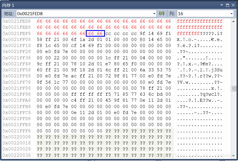
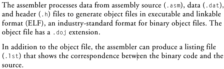
Figure 1-1 shows a graphical overview of the assembly process. The figure shows the preprocessor processing the assembly source (.asm) and header (.h) files.

By default, the assembler processes an intermediate file to produce a binary object file (.doj) and an optional listing file (.lst).

image-20210520012328329

编写

  • Assembler directives are coded in assembly source files.

  • The directives allow you to define variables, set up hardware features, and identify program sections for placement within processor memory.

  • The assembler uses directives for guidance as it translates a source program into object code.

注意:

  • Do not use a word processor that embeds special control codes in the text.

  • Use an .asm extension to source file names to identify them as assembly source files.

可以使用像 batch-filemakefile 这样的命令行工具来汇编你的源文件。

列表文件还提供了关于导入的C语言数据结构的信息。

问题解决

问题一

现象:出现如下图所示的头文件缺少

image-20210520090023689

原因.boj文件和其所依赖的 .h 头文件相对路径不一致,或项目文件的绝对路径与原来创建时不一致。

例如:从文件 Debug/system/startup_Idf/app_IVT.doj 中可以看出,该文件的创作者是将其放置在 D:\ADSP\workspace\LED_test\Debug 下的,因此需要改变该项目文件的位置。

解决方法:在原创作者的绝对路径下放置该项目文件。

image-20210520090936369

I2C基本通信规则

标准《NXP_UM10204_I2C-bus specification and user manual》

IIC总线是一个事实上的世界标准,现在已经在50多家公司生产的1000多种不同的IC中实施。

此外,多功能的IIC总线被用于各种控制架构,如系统管理总线(SMBus)、电源管理总线(PMBus)、智能平台管理接口(IPMI)、显示数据通道(DDC)和高级电信计算架构(ATCA)。

本文件帮助设备和系统设计者了解IIC总线的工作原理并实现工作应用。描述了各种操作模式。它包含了对IIC总线数据传输、握手和总线仲裁方案的全面介绍。详细的章节涵盖了IIC总线在每种工作模式下的时序和电气规范。

IIC兼容芯片的设计者应将该文件作为参考,并确保新设备满足该文件中规定的所有限制。包含IIC器件的系统的设计者应审查本文件,并参考各个组件的数据表。

——翻译自标准文件

IIC(Inter-Integrated Circuit)是一种通用的总线协议。它是由Philips(飞利浦)公司,现NXP(恩智浦)半导体开发的一种简单的双向两线制总线协议标准。

对于硬件设计人员来说,只需要2个管脚,极少的连接线和面积,就可以实现芯片间的通讯,对于软件开发者来说,可以使用同一个IIC驱动库,来实现实现不同器件的驱动,大大减少了软件的开发时间。极低的工作电流,降低了系统的功耗,完善的应答机制大大增强通讯的可靠性。

术语

image-20210514111033910

术语 释义
总线 传输数据的通路
传送者 传输数据至总线的设备
接收者 从总线上接受数据的设备
主(机) 主动开启传输、生成时钟信号 并 主动结束传输的设备
从(机) 由主机寻址的设备
多主(机) 在不损坏数据传输的情况下允许多主机可以试图同时控制总线
仲裁 确保在有多个主机同时试图控制总线的情况下,只允许一个主机这样做,而且仲裁成功的信息不会被(其他设备)破坏的程序。
同步 确保两个及以上设备其时钟信号的同步

以下这个图应该可以较好地解释“多主机”的概念,多个主机可以同时向外发出传输数据的申请,也可以主动结束其数据传输。虽然,IIC降低了总线复用的成本,但仍需要“仲裁”机制来解决多个主机之间的无序竞争状态。

image-20210514112114667

硬件要求

电气特性

根据要求,I2C的高电平有效值要达到输入参考电压(一般是VDD)的0.7倍以上,低电平有效值需要达到输入参考电压的0.3倍以下。

image-20210618143438565

总线硬件要求

通过 串行数据(SDA,Serial Data)和 串行时钟(SCL,Serial Clock)两条线路对设备进行连接。

每个设备都通过自身的通信设备地址进行互相辨别,且每个设备都可以当发送者或接收者,取决于设备自身的功能定义。

标准传输速率

各模式、速率及其传输方向见下方表格。

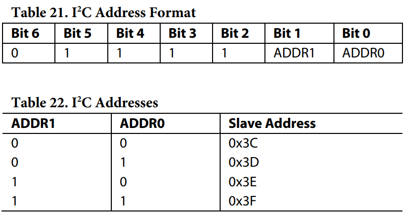
Data on the IIC-bus can be transferred at rates of up to 100 kbit/s in the Standard-mode, up to 400 kbit/s in the Fast-mode, up to 1 Mbit/s in Fast-mode Plus, or up to 3.4 Mbit/s in the High-speed mode.

MODE RATE TRANSFER DIRECTION DOWNWARD COMPATIBLE WITH
STANDARD 100 Kbit/s bidirectional /
FAST 400 Kbit/s bidirectional STANDARD
FAST-PLUS 1 Mbit/s bidirectional STANDARD / FAST
HIGH-SPEED 3.4 Mbit/s bidirectional STANDARD / FAST / FAST-PLUS
ULTRA-FAST 5 Mbit/s unidirectional /

编码协议

以下协议要求适用于双向通信模式(不包括ULTRA-FAST模式下的单向通信)

逻辑电平规定

由于IIC的接入设备众多(如CMOS、NMOS、Bipolar等),因此逻辑电平0和逻辑电平1(的电压)并不是固定不变的,这取决于VDD的电平。

输入参考电平会被控制在VDD电平的30%~70%之间。 VIL = 0.3 * VDD;VIH = 0.7 * VDD

某些传统设备的输入电平会被固定在1.5V(VIL)和3.0V(VIH),但新设备都要求是 30%VDD 及 70%VDD

注意:VIL、VIH、VOL、VOH都是以参考电压作为基准的,即要达到某个电压的百分之多少时,才能够被认为是 逻辑电平0逻辑电平1 。例如,可将VIL 视作当VDD下降到只有30%及以下时,为逻辑电平0,30%VDD是其逻辑电平的最高阈值;同理可得 VIH ;超过这个值而未到达70%的中间态则为不确定态。

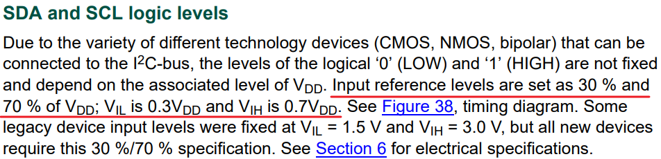
Due to the variety of different technology devices (CMOS, NMOS, bipolar) that can be connected to the IIC-bus, the levels of the logical ‘0’ (LOW) and ‘1’ (HIGH) are not fixed and depend on the associated 
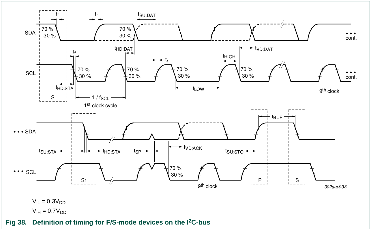
level of VDD . Input reference levels are set as 30 % and 70 % of VDD ; VIL is 0.3VDD and VIH is 0.7V DD .

See Figure 38, timing diagram. Some legacy device input levels were fixed at VIL = 1.5 V and VIH = 3.0 V, but all new devices require this 30 %/70 % specification.

image-20210514134830615

时序正确性

  • SDA上的数据必须在SCL高电平期间保持稳定,即不能在SCL高电平期间发生翻转(后见原因),只有在SCL低电平时可以翻转。
  • 时钟脉冲信号生成要先于数据传送。

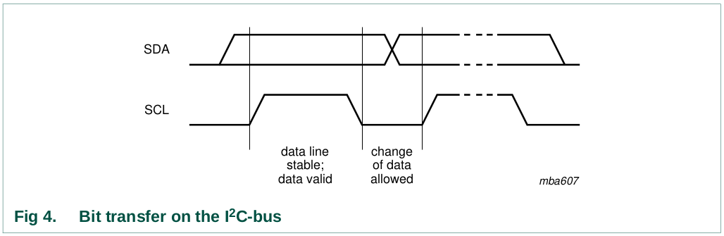
The data on the SDA line must be stable during the HIGH period of the clock. The HIGH or LOW state of the data line can only change when the clock signal on the SCL line is LOW (see Figure 4). One clock pulse is generated for each data bit transferred.

image-20210514141512136

开始及结束标志

  • 传输开始时必须以一个 开始 信号作为标志,结束时必须以一个 结束 信号作为标志。

  • 开始信号 是以SCL为高电平时的 SDA电平的由高转低 作为标志,结束信号 是以SCL高电平时的 SDA电平的由低转高 作为标志。

  • 开始和结束标志必须由主设备控制。

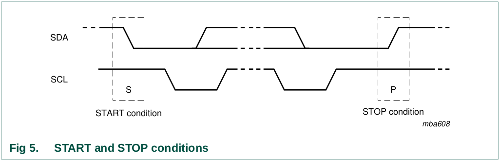
All transactions begin with a START (S) and are terminated by a STOP (P) (see Figure 5). A HIGH to LOW transition on the SDA line while SCL is HIGH defines a START condition. A LOW to HIGH transition on the SDA line while SCL is HIGH defines a STOP condition.

image-20210514142116674

开始字节

image-20210515150526897

dummy acknowledge (HIGH) : 无声确认???

总线状态

总线具有两种状态,繁忙(Busy)和 空闲(Free),即 SDA电平 “开始” 后,总线进入繁忙状态, SDA电平 “结束” 后,总线进入空闲状态。

注意:在总线繁忙期间,发生重复的“开始”状态(而不是“结束”状态),由于“重复开始”和 “开始” 功能相同,为了方便,统称为 “开始”,除非特殊说明为 “重复开始”。

The bus stays busy if a repeated START (Sr) is generated instead of a STOP condition. In this respect, the START (S) and repeated START (Sr) conditions are functionally identical. For the remainder of this document, therefore, the S symbol is used as a generic term to represent both the START and repeated START conditions, unless Sr is particularly relevant.

传输比特位

  • SDA线上的字节传输必须满足8位长度。
  • 每次传输数据的字节数不受限制。
  • 每个字节数后都需要跟一个确认位(Acknowledge bit)
  • 当从机无法完整接收或传输一个完整的数据字节时,例如正在产生内部中断等,除非其完成内部的某些功能,否则该从机将能够一直拉低SCL的电平,强制让主机一直处于等待状态。只有当从机准备好接收下一个完整的字节并释放SCL时,数据传输才会继续。

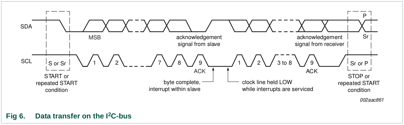
Every byte put on the SDA line must be eight bits long. The number of bytes that can be transmitted per transfer is unrestricted. Each byte must be followed by an Acknowledge bit.

Data is transferred with the Most Significant Bit (MSB) first (see Figure 6). If a slave cannot receive or transmit another complete byte of data until it has performed some other function, for example servicing an internal interrupt, it can hold the clock line SCL LOW to force the master into a wait state. Data transfer then continues when the slave is ready for another byte of data and releases clock line SCL.

image-20210514144620803

确认标志

  • 每个字节(8比特)后都跟着一个确认位,即前8位数据,第9位确认。
  • SCL上的时钟信号由主机产生,包括确认位的的第九个时钟脉冲
  • SDA线并不是由主机一直占有的,每发送完一个完整字节后,主机都会释放SDA线,由从机进行数据确认。
  • 发送者在确认时钟脉冲期间释放SDA线,以便接收者可以将SDA线拉低,并且在该时钟脉冲的高电平期间保持稳定的低电平。
  • 对于设置(set-up)和保持(Hold)的时间,都应该依照表10中只针对各种不同模式的要求进行设置。
  • 如果SDA电平在第九个时钟脉冲时仍保持高电平,则被定义为 “未确认状态”。则此时主机可以发送一个“结束”标志来结束当前连接,或发送一个“开始”标志来开启一次新的传送。

即,此时(第9个脉冲时)SDA的控制权已经被mater释放了,但仍为高电平,slave可以在这第9个时钟脉冲高电平期间获得控制权,如果确认收到数据,则将电平拉低,否则不拉低。

image-20210607141115024

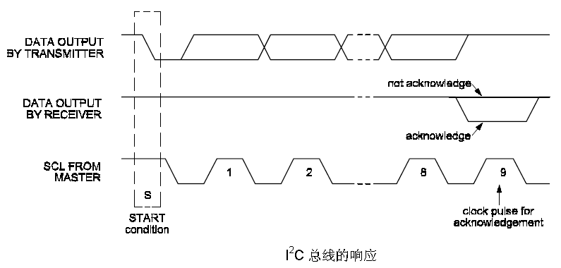
The acknowledge takes place after every byte. The acknowledge bit allows the receiver to signal the transmitter that the byte was successfully received and another byte may be sent. The master generates all clock pulses, including the acknowledge ninth clock pulse.

The Acknowledge signal is defined as follows: the transmitter releases the SDA line during the acknowledge clock pulse so the receiver can pull the SDA line LOW and it remains stable LOW during the HIGH period of this clock pulse (see Figure 4). Set-up and hold times (specified in Section 6) must also be taken into account.

When SDA remains HIGH during this ninth clock pulse, this is defined as the Not Acknowledge signal. The master can then generate either a STOP condition to abort the transfer, or a repeated START condition to start a new transfer.

以下为五种“未确认/未应答”的可能情况:There are five conditions that lead to the generation of a NACK:

  1. 传输地址错误:No receiver is present on the bus with the transmitted address so there is no device to respond with an acknowledge.
  2. 实时处理中:The receiver is unable to receive or transmit because it is performing some real-time function and is not ready to start communication with the master.
  3. 数据/代码未定义:During the transfer, the receiver gets data or commands that it does not understand.
  4. 正在传输中:During the transfer, the receiver cannot receive any more data bytes.
  5. 未收到结束信号(收发身份未转换):A master-receiver must signal the end of the transfer to the slave transmitter.

时钟同步

任意几个主机都可能同时发起数据传输请求,此时只有一个主机和一个从机可以掌握总线进行通信,此时需要通过 时间同步仲裁 完成对总线的调配。

在单机系统(Single Master System)中,不需要时钟同步和仲裁。

时钟同步是通过IIC接口与SCL线的有线-AND连接进行的。

这意味着SCL线上的高电平到低电平的转换会导致相关的主站开始对其低电平周期进行计数(如图7的CLK2),一旦一个主站时钟 CLK1 变为低电平,它就会将SCL线电平拉低,并保持在这个状态,直到另一个时钟 CLK2 达到高电平状态。

然而,如果时钟 CLK2 仍在其低电平周期内,CLK1 的低电平到高电平转换可能不会改变SCL线的状态。

因为SCL线被具有最长的低电平周期的主站 CLK2 保持为低电平,而在这段时间内,低电平周期较短的主站 CLK1 进入高电平等待状态。

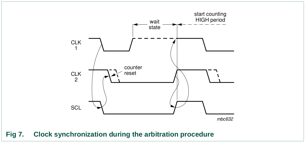
Clock synchronization is performed using the wired-AND connection of IIC interfaces to the SCL line. This means that a HIGH to LOW transition on the SCL line causes the masters concerned to start counting off their LOW period and, once a master clock has gone LOW, it holds the SCL line in that state until the clock HIGH state is reached (see Figure 7). However, if another clock is still within its LOW period, the LOW to HIGH transition of this clock may not change the state of the SCL line. The SCL line is therefore held LOW by the master with the longest LOW period. Masters with shorter LOW periods enter a HIGH wait-state during this time.

当所有相关的主控器都结束了他们的低电平周期,时钟线被释放并变成高电平。

然后,在主站时钟和SCL线的状态之间没有差异,所有的主站开始计算他们的高电平周期。

第一个完成其高电平周期的主站再次将SCL线拉到低电平。这样,就产生了一个同步的SCL时钟其低电平周期由具有最长时钟低电平周期的主站决定其高电平周期由具有最短时钟高电平周期的主站决定

image-20210514170202184

竞争仲裁

仲裁和同步一样,是指只有在系统中使用一个以上的主站时才需要的协议的一个部分。注意,从机不参与仲裁程序。

一个主站只有在总线空闲时才可以开始传输。两个主站可以在START条件的最小保持时间(tHD;STA)内产生一个START条件,从而在总线上产生一个有效的START条件。然后需要进行仲裁,以确定哪个主站将完成其传输。

仲裁是逐位进行的。在每个比特期间,当SCL为高电平时,每个主站检查SDA电平是否与其所发送的内容相符,期间可能需要很多比特,只要传输的内容相同,两个主站实际上可以无误地完成整个信息传输过程。

当一个主站第一次试图发送一个高电平,但检测到SDA电平为低电平时,主站知道它已经失去了仲裁,并关闭其SDA输出驱动器。在其他主站被仲裁过程中,正在传输其信息的主站将继续其传输,没有信息丢失。

失去仲裁的主站可以产生时钟脉冲,直到它失去仲裁的字节结束,并且必须在总线空闲时重新尝试传输。

如果一个主站也包含了一个从站功能,并且它在寻址阶段失去了仲裁,有可能获胜的主站正试图对它进行寻址。因此,失败的主站必须立即切换到其从站模式。

图8显示了两个主站的仲裁程序。可能涉及更多,这取决于有多少个主站连接到总线上。

当产生DATA1的主站的内部数据电平与SDA线上的实际电平有差异时,DATA1的输出被关闭。这并不影响由获胜主站发起的数据传输。

image-20210515142633906

通用寻址

image-20210515172907284
image-20210515172945861
image-20210515172958184

软复位

在发送general call (0000 0000)后,再发送一个 0000 0110 (06h) ,这样两个具有先后顺序的字节来定义软复位。

首先,这种软复位是可选 ,并不是所有设备都会对软复位指令进行响应。

在收到这2个字节的序列时,所有被设计为响应一般调用地址的设备都会复位,并接收其地址的可编程部分。

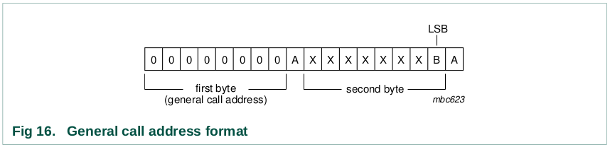
On receiving this 2-byte sequence, all devices designed to respond to the general call address reset and take in the programmable part of their address.

必须采取预防措施,确保设备在施加电源电压后没有拉低SDA或SCL线,因为这些低电平会阻断总线。

总线复位

SCK信号一直卡在低电平的事件较少发生。

  • 如果IIC总线设备拥有硬件复位输入,则可以通过优先程序启用硬件中断复位来重置总线。
  • 如果没有硬件复位输入,则通过给设备循环供电,激活强制性的内部开机复位(POR)电路。

SDA信号如果一直卡在低电平。

  • 则主机应该发送九次SCL时钟脉冲,此时令SDA保持低电平的设备在收到九次脉冲后应主动释放总线。

  • 如果九次脉冲没有用,则启用硬件中断复位或循环供电来清除总线。

设备ID

可选的3字节只读设备ID编码(an optional 3-byte read-only ):

  • 12位是设备制造商编号,具有独一无二性
  • 9位零件ID,由设备制造商写入
  • 3位模具/晶元版本,由设备制造商写入

image-20210515152141963

  1. 启动条件

  2. 主站发送保留设备ID的 IIC 总线地址,后面的R/W位设置为0(写):1111 1000

  3. 主站发送从属地址。LSB是一个 "不关心"的值,只有一个设备必须确认这个字节(拥有IIC总线从属地址的设备)。

  4. 主站发送一个 Re-START 条件。

备注:在 STOP 条件之后,再加上一个 START 条件,就会重置从属状态机,无法进行设备ID读取。另外,在 STOP 条件或 Re-START 条件之后,对另一个从属设备的访问也会重置从属状态机,无法执行Device ID读取。

  1. 主站发送保留设备ID的 IIC 总线地址,后面的R/W位设置为 1(读):1111 1001

  2. 可以进行设备ID读取,从12个制造商位开始(第一个字节+第二个字节的4个MSB),然后是9个部件识别位(第二个字节的4个LSB+第三个字节的5个MSB),然后是三个芯片修订位(第三个字节的3个LSB)。

  3. 主站通过NACKing最后一个字节来结束读取序列,从而重置从属设备的状态机,允许主站发送 STOP 条件。

    备注:设备ID的读取可以随时通过发送NACK来停止。

如果主站在第三个字节之后继续ACK,从站就会滚回第一个字节,并继续发送设备ID序列,直到检测到 NACK。

ADI-Codec I2C开发

ADI

物理接口

存在由ADI官方提供的评估板(和MediaWorks的板) 和 开发第一板(量产板)之间的引脚定义差别,一开始使用的是评估板的DPI 11 和 12引脚,即 DPI_P11SDADPI_P12SCLK。后来发现作为时钟引脚的DPI无法被控制,转而使用 DPI 11 和 13。即 DPI_P11SDADPI_P13SCLK

image-20210524112141809

image-20210615083241938

MediaWorks核心板J3引脚排示意图

以下描述均以评估板为例,DIY板不一定适用。

插口(Jumper)定义

image-20210427165847934

时钟及PLL

  1. 1772的工作频率为12.288兆赫,而如果过要设置PLL,PLL输出一定是24.576兆赫。
  2. 通过 MCLKIN 端为codec提供核心时钟信号,可接入8至27兆赫信号。
  3. 通过对 0x00000x0005 的寄存器进行写入修改PLL。
  4. PLL模式要被设置为分数或整数,则取决于MCLK的输入频率。
  5. 在时钟信号达到PLL前,时钟信号会经过整数时间分频器以确保时钟频率符合要求;可以通过设置 0x0005 的bit[2:1]来设置其分频率。
  6. 要使用PLL时,首先要明确PLL输出频率是多少,当PLL信号与时钟信号是整数倍关系时才需要使用整数分频器。
image-20210513093158863

以下列举了整数型及分数型分频器的参数设置:

image-20210513093047973

评估板电路图

image-20210513092007130

输入输出

评估板电路图

image-20210513090414605

第0及第1通道

以下为codec芯片对引脚的定义,在提供一个接地端,构成TRS是完全没有问题,但是codec的定义和其评估板的外围电路设计有所区别。

image-20210513083636462

正常3.5mm音频接口为TRS接口,其中T虽然为VCC(通常是),R作为音频信号输入,而S为接地端,且T和R可共同作为左右声道分别进行输入。(也有T和S定义相反的设计)

但是按上述电路进行接线时,相当于TS接口(单声道)接线模式,却又不完全相同:

  • 使用 MICBIASx 对14接口进行供电,此时Tip端是VCC。
  • Ring端接13接口,充当Sleeve端(而实际上的Sleeve端因已经接地,可以不进行连接)。
  • 由Ring(AIN1REF)和Tip(AIN1)共同构成了TS单声道接线模式。

第2及第3通道

  • 2/3输入通道是复用立体声通道,即1通道和0通道都可以单独接入音源,在物理音频接口上独立,但第2/3通道是在一起的,共用一个物理通道。UG第7页中也有提到。

image-20210427104818097

image-20210427105655639

  • 有四个单端输入通道可以设置为麦克风信号或线路信号,一个双立体声数字输入信号通道和也可被用于单端输出的两个差分(differential)输出。

I2C通信

时序

图85展示了 单字主写模式 的时序。每9个时钟脉冲,1772都会拉低一次SDA的电平以表示确认收到。

图86展示了 多字主写模式 的时序。此图展示了2个字节大小数据(例如程序)的写入过程。1772会在每两个字节后增加一次子地址寄存器,因为被使用的子地址对应着 2字节 长度的寄存器或内存区域

图87展示了 单字主写模式后转变为 单字主读模式 的时序。1772作为从机接受数据后发送确认标志,主机立即发起重复开始的 单字主读模式,由从机发送至主机。

图88展示了 多字主读模式 的时序,展示了读取目标字节为2bytes的示例。此处上述黄底字重复。其他地址范围可能有不同的字长,从一个到四个字节不等。ADAU1772总是对子地址进行解码,并设置自动递增电路,使地址在适当的字节数后递增。

image-20210518105918652

S = 开始 标志

P = 停止 标志

AM = 主机确认标志

AS = 从机确认标志

接口

USBi接口

​ 《SigmaStudio_USBi_to_EZ-Board_Adapter_Schematic-Rel_0.1.pdf》中对接口的定义,总共需要4个引脚,分别是1、3、4、10,对应着 SCL / SDA / VCC / GND;

image-20210518112823329

1772接口

需要用到的接口是 SCL/SCLKSDA/MISO

image-20210518192233133

ADDR0 和 ADDR1 分别对应的是控制接口(CONTROL PORT)上的 CLATCHCDATA 针脚。

image-20210607145600052

image-20210518112823329

BIT_6 BIT_5 BIT_4 BIT_3 BIT_2 BIT_1 / ADDR1 / CDATA BIT_0 / ADDR0 / CLATCH ADDRESS
0 1 1 1 1 0 0 0x3C
0 1 1 1 1 0 1 0x3D
0 1 1 1 1 1 0 0x3E
0 1 1 1 1 1 1 0x3F

21479接口

《ADSP-21479 EZ-Board Evaluation System Manual》,需要用到的接口是 SPI_CLK(DPI_P3)SPI_MISO(DPI_P2)

image-20210518113240492

对应评估板上的针脚接口如下图示 24(DPI_P3) 和 27(DPI_P2) 接口。

image-20210519114333234

设备地址

主机每次发送8位数据,其中最低的一位由主机发送标识读/写位。逻辑电平1是读,逻辑电平0是写。

通过I2C方式进行连接的从机,其设备地址是7位数(1-7,对应表21是bit0-bit6),表21提供了1772的设备地址,ADDR1ADDR0 位置可以通过接入pin的方式自由设置,即输入引脚的电平不同,每个1772都能够拥有4个独特的地址。此类方式允许多块1772接入同一I2C总线。

  • 即,默认情况下从机地址为 0x3C ,可以设置成其他:0x3D , 0x3E, 0x3F
  • 每个SDA和SCL线都应该接入一个2.0KΩ的升压电阻,但不应该高过IOVDD。
image-20210519093557617

image-20210519094454381

相关问答

Q: what is the macro SIGMA_WRITE_DELAY supposed to do? Is it a simple delay? Why are there parameters regarding the device I2C address, data and length? A: This macro is used for applications that need to pause the data writes for a specific purpose. 
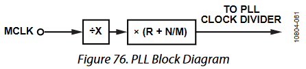
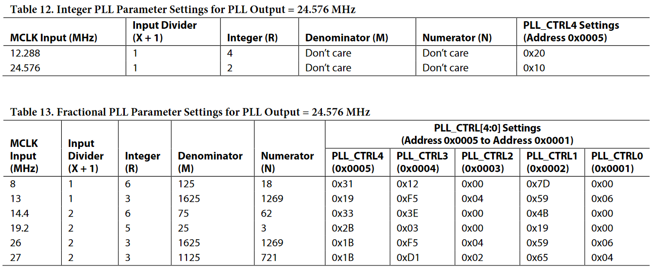
For example, if you need time for the PLL to be set before starting to write to the rest of the registers. It could be used as a simple delay, you’ll need to specify the device address always because some applications can require more than one DSP; the length is just the address byte length (could be 1 or 2 byte length) and data is the value in hex that represents the total time in milliseconds (that is up to the micro controller clock speed). The reason length is used, is that some DSPs work with one and some other require two address bytes.

<SigmaStudioFW.h> contains a lot of macros to be defined. What I found by examinating all the code is that what macros need to be defined depend on what you want to perform with your microcontroller.

If you only need to load a DSP program with a call to default_download(), well, you only need (at least for the ADAU1761)

to implement the two macros:

  • SIGMA_WRITE_REGISTER_BLOCK

  • SIGMA_WRITE_DELAY

The first one is the basis of all the loading of data into program ram, parameter ram, and registers. The second one is only a delay (to be exact it serves to wait for the PLL to lock, in any case most of the times it can be implemented as a simple delay).

If you want to use sequences, that is to implement some control of the DSP running with your microcontroller, you will probably need to implement the other macros. In particular if you will control volume sliders you will need to implement the conversion macros for integer or float to the internal 5.23 representation. You can search elsewhere on the forum, I saw some of this code.

开发代码

ADI和Codec之间的I2C通信可以通过两种方式进行,第一种是操作21478上面的TWI寄存器,需要查看《HWR》以获取更多信息。第二种是学会控制引脚高低电平,通过高低电平模拟寄存器操控来读取和写入I2C设备。

在开发过程中,先使用的第一种方式对TWI寄存器进行操控,但发现21479中有某个寄存器无法写入,故放弃。下面提供第二种方式中需要用到的三个文件,分别是 TWI.hTWI.cSigmaStudioFW.h 。经调试,以下代码可以正常收发数据,实现对从设备的读/写。

TWI.c

1
2
3
4
5
6
7
8
9
10
11
12
13
14
15
16
17
18
19
20
21
22
23
24
25
26
27
28
29
30
31
32
33
34
35
36
37
38
39
40
41
42
43
44
45
46
47
48
49
50
51
52
53
54
55
56
57
58
59
60
61
62
63
64
65
66
67
68
69
70
71
72
73
74
75
76
77
78
79
80
81
82
83
84
85
86
87
88
89
90
91
92
93
94
95
96
97
98
99
100
101
102
103
104
105
106
107
108
109
110
111
112
113
114
115
116
117
118
119
120
121
122
123
124
125
126
127
128
129
130
131
132
133
134
135
136
137
138
139
140
141
142
143
144
145
146
147
148
149
150
151
152
153
154
155
156
157
158
159
160
161
162
163
164
165
166
167
168
169
170
171
172
173
174
175
176
177
178
179
180
181
182
183
184
185
186
187
188
189
190
191
192
193
194
195
196
197
198
199
200
201
202
203
204
205
206
207
208
209
210
211
212
213
214
215
216
217
218
219
220
221
222
223
224
225
226
227
228
229
230
231
232
233
234
235
236
237
238
239
240
241
242
243
244
245
246
247
248
249
250
251
252
253
254
255
256
257
258
259
260
261
262
263
264
265
266
267
268
269
270
271
272
273
274
275
276
277
278
279
280
281
282
283
284
285
286
287
288
289
290
291
292
293
294
295
296
297
298
299
300
301
302
303
304
305
306
307
308
309
310
311
312
313
314
315
316
317
318
319
320
321
322
323
324
325
326
327
328
329
330
331
332
333
334
335
336
337
338
339
340
341
342
343
344
345
346
347
/*
* TWI.C
*
* Created on: 2021年6月16日
* Author: 431240
*/


#include"TWI.H"

//宏定义
#define HWDELAY {HWDelay(MINDT);} //延时函数
#define MTWACK {TWIMWaitAck();} //Master Transmitter Wait Ack


// ------------------------------------------------------------------------------------
// 全局变量声明
DADDR tempDevAddr = 0x00; //临时设备地址存储比对变量,及其初始化
RADDR tempRegAddr = 0x00; //临时寄存器地址存储对比变量,及其初始化
TWIDATA bit = 0;

static TWIDATA dataRead = 0; //用于观察数据写入后再读取的状态
//static TWIDATA addrAckRead = 0; //调试观察用
//static TWIDATA regAckRead = 0; //调试观察用
//static TWIDATA dataAckRead = 0; //调试观察用

static DADDR targetAddr = 0x00;

// ------------------------------------------------------------------------------------
// 函数定义
extern void TWITimerIsr(int delayTime){ //用于产生中断高/低电平延时的定时器中断(句柄)
//需要自定义,涉及到定时器调用相关函数,请自行查阅手册
}


extern void HWDelay(float hwDelayTime){ // 定义硬件延时(单位微秒)

#ifdef HWDELAY_CORETIMER
timer_set(6400*hwDelayTime, 6400*hwDelayTime);
timer_on();
timer_off();
#endif

#ifdef HWDELAY_SYSWAITNOP
SysWaitNOP(HW_SYSWAITNOP_TIME); //此处使用循环函数进行延时
#endif

}


extern void TWIInit(void){ //初始化函数
#ifdef EVA_21479
SRU(FLAG13_O,DPI_PB13_I);
SRU(FLAG11_O,DPI_PB11_I);

SRU(HIGH,DPI_PBEN13_I);
SRU(HIGH,DPI_PBEN11_I);

sysreg_bit_set( sysreg_FLAGS, (FLG11O|FLG13O) );
sysreg_bit_clr( sysreg_FLAGS, (FLG11|FLG13) );

#else
SRU(FLAG8_O,DPI_PB08_I);
SRU(FLAG7_O,DPI_PB07_I);

SRU(HIGH,DPI_PBEN08_I);
SRU(HIGH,DPI_PBEN07_I);

sysreg_bit_set( sysreg_FLAGS, (FLG7O|FLG8O) );
sysreg_bit_clr( sysreg_FLAGS, (FLG7|FLG8) );
#endif

SDA_OUT;
SCL_OUT;

}


extern int TWIStart(void){ //启动函数
SDA_OUT; //设置为数据输出方向

S_SDA;
S_SCL;
HWDELAY;

C_SDA;
HWDELAY;

return 1;
}


extern void TWIReStart(void){ //重启动函数
SDA_OUT;

C_SCL;
HWDELAY;

S_SDA;
S_SCL;
HWDELAY;

C_SDA;
HWDELAY;
}


extern void TWIStop(void){ //停止
SDA_OUT;

C_SCL; //modified by liewzheng
C_SDA; //在时钟信号拉高之前先拉低数据信号
HWDELAY; //modified by liewzheng

S_SCL;
HWDELAY;

S_SDA; //在时钟信号高电平时拉高数据信号
HWDELAY;
}


extern void SendWithoutAck(void){ //发送无需确认
SDA_OUT;

C_SDA;
HWDELAY;

S_SCL;
HWDELAY;

C_SCL;

SDA_IN;
}


extern TWIDATA TWIMWaitAck(void){ //等待从机确认并读取确认信号
C_SCL;
SDA_IN;
HWDELAY;

S_SCL;
if(!READ_SDA){
HWDELAY;
return 0;
}
else{
HWDELAY;
return 1;
}

}


extern void TWISendByte(TWIDATA SentByte){ //发送一个字节
TWIDATA bit_count = 8;
SDA_OUT;

while(bit_count--){
if(SentByte & 0x80){
C_SCL; //先拉低SCL
S_SDA; //1则置高
}
else{
C_SCL; //先拉低SCL
C_SDA; //0则置低
}
SentByte <<= 1; //前移一位
HWDELAY;

S_SCL;
HWDELAY;
}
}


extern void TWIWriteByte(DADDR DevAddr, RADDR RegAddr, TWIDATA *Data){
if(TWIStart() != 0){
TWISendByte(DevAddr);
MTWACK;
// addrAckRead = TWIMWaitAck(); //测试时使用

TWISendByte(RegAddr>>8); //采用16bit寻址空间,先发送高8位地址,在发送低8位地址
MTWACK;
// regAckRead = TWIMWaitAck();

TWISendByte(RegAddr);
MTWACK;
// regAckRead = TWIMWaitAck();

TWISendByte(*(Data+0));
MTWACK;
// dataAckRead = TWIMWaitAck();
}
TWIStop();
}


extern void TWIWriteByteContinuly(DADDR DevAddr, RADDR RegAddr, int length, TWIDATA *Data){ //连续发送数据,相同设备无暂停
TWIStart();

TWISendByte(DevAddr);
MTWACK;

TWISendByte(RegAddr>>8); //采用16bit寻址空间,先发送高8位地址,在发送低8位地址
MTWACK;

TWISendByte(RegAddr);
MTWACK;

for(int i = 0;i <length; i++){
TWISendByte(*(Data+i));
MTWACK;
}

TWIStop();
}


extern DADDR TWIDAddrTest(void){ // 设备地址测试验证
DADDR MAXADDR = 0x7F; //设置最大地址为0x7F,此处仅测试7bit设备地址,10bit不测试
DADDR tempAddress = 0x00; //设置设备最小值

for(; tempAddress <= MAXADDR; tempAddress++) //设置for循环
{
TWISendByte((TWIDATA) tempAddress);//发送设备地址
if(TWIMWaitAck()) return tempAddress; //等待应答,如果应答,则返回正确的设备地址
}
return 0xFF; //否则(运行结束时)返回0xFF。
}


extern void TWISCL(void){ //Only used in Test mode
C_SCL;
S_SDA;
HWDELAY;
S_SCL;
C_SDA;
HWDELAY;
}


// ------------------------------------------------------------------------------------
// 以下函数未使用。
extern void MRSendAck(void){ //Only in Master-receiver mode, 发送确认信号给slave,仅在主-收模式时使用
SDA_OUT;

C_SDA;
HWDELAY;

S_SCL;
HWDELAY;

C_SCL;

SDA_IN;
}


extern TWIDATA TWI_read_byte(DADDR DevAddr, RADDR RegAddr){
static TWIDATA RetVal = 0;

TWIStart();

TWISendByte( DevAddr ); //发送设备地址和W标志位,等待确认,据Figure87
MTWACK;

TWISendByte(RegAddr>>8); //发送MSB寄存器地址
MTWACK;
TWISendByte(RegAddr); //放LSB寄存器地址
MTWACK;

TWIReStart(); //重启动并发送设备地址

TWISendByte( DevAddr+1 ); //发送设备地址和R标志位,等待确认
MTWACK;

RetVal = TWIReceiveByte();
SendWithoutAck();

TWIStop();

return RetVal; //返回目标寄存器的值
}


extern void TWI_write_2_byte(DADDR DevAddr, RADDR RegAddr, TWIDATA Data1, TWIDATA Data2){
if (TWIStart() != 0){
TWISendByte(DevAddr); //1、发送设备地址
MTWACK;
TWISendByte(RegAddr); //2、发送寄存器地址
MTWACK;
TWISendByte(Data1); //3、发送寄存器数据 for PORT 0
MTWACK;
TWISendByte(Data2); //4、发送下一个寄存器数据 for PORT 1
MTWACK
}
TWIStop();

}


extern TWIDATA TWIReceiveByte(void){ //作为主机,读取从机字节
TWIDATA Byte_count = 8;
TWIDATA RetVal = 0;

C_SCL;
HWDELAY;

SDA_IN;

while (Byte_count--){
S_SCL;
RetVal <<= 1;
if (READ_SDA){
RetVal = RetVal | 1;
}
HWDELAY;
C_SCL;
HWDELAY;
}

return RetVal;
}

extern DADDR TWIDevAddrTest(char addressBit){
switch(addressBit){
case (7):
for(targetAddr = 0x00 ; targetAddr < 0x7F; targetAddr++){
TWIStart();
TWISendByte(targetAddr<<1); //尝试过target和target<<1都不行
if(!TWIMWaitAck() ) {
TWIStop();
return targetAddr;
}
else TWIStop();
}
break;
case (10): //此处需要自定义
break;
default:
return (0x00);
}
return (0x00);
}

TWI.h

1
2
3
4
5
6
7
8
9
10
11
12
13
14
15
16
17
18
19
20
21
22
23
24
25
26
27
28
29
30
31
32
33
34
35
36
37
38
39
40
41
42
43
44
45
46
47
48
49
50
51
52
53
54
55
56
57
58
59
60
61
62
63
64
65
66
67
68
69
70
71
72
73
74
75
76
77
78
79
80
81
82
83
84
85
86
87
88
89
90
91
92
93
94
95
96
97
98
99
100
101
102
103
104
105
106
107
108
109
110
111
112
/*
* TWI.H
*
* Created on: 2021年6月16日
* Author: 431240
*/

#pragma once

#include <sru21479.h>
#include <def21479.h>
#include <cdef21479.h>
#include <signal.h>
#include <21479.h>
//#include "Common.h"
#include "ADDS_21479_EzKit.h"

/*-----------------------------------------------------------------------------------
* 调试用宏定义
-----------------------------------------------------------------------------------*/

#define NACK 0 //不用从机确认
#define ACK 1 //需要从机进行确认

//#define HWDELAY_CORETIMER
#define HWDELAY_SYSWAITNOP

//#define EVA_21479 1 //如果是评估板


/*-----------------------------------------------------------------------------------
* 数据类型定义
-----------------------------------------------------------------------------------*/
typedef unsigned int DADDR; //设备地址数据类型定义
typedef unsigned int RADDR; //寄存器地址数据类型定义
typedef unsigned char TWIDATA; //数据发送的数据类型定义

// ------------------------------------------------------------------------------------
// 引脚定义:RST 定义为 DPI_12 , SDA 定义为 DPI_11 , SCL 定义为 DPI_13
// 在试制板中,两块codec均与21479的第7、8引脚连接,DPI_07定义为SDA, DPI_08定义为SCL

#define RST_OUT {SRU(HIGH, DPI_PBEN12_I); } //设置复位信号输出方向
#define S_RST {SRU(LOW, DPI_PB12_I); } //拉低电平以设置复位信号
#define C_RST {SRU(HIGH, DPI_PB12_I);} //拉高电平以释放复位信号

#ifdef EVA_21479
#define SDA_OUT {SRU(HIGH, DPI_PBEN11_I); } //设置SDA输出方向
#define SDA_IN {SRU(LOW, DPI_PBEN11_I); } //设置SDA输入方向
#define C_SDA {SRU(LOW, DPI_PB11_I); } //拉低SDA以清除数据
#define S_SDA {SRU(HIGH, DPI_PB11_I); } //拉高SDA

#define SCL_OUT { SRU(HIGH, DPI_PBEN13_I); } //SCL设定为输出方向的定义
#define C_SCL {SRU(LOW, DPI_PB13_I); } //拉低SCL以清除时钟
#define S_SCL {SRU(HIGH, DPI_PB13_I); } //拉高SCL以设置时钟

#define READ_SDA (*pDPI_PIN_STAT & DPI_PB11) //从SDA读取数据
#define READ_SCL (*pDPI_PIN_STAT & DPI_PB13) //从SCL读取数据

#else //量产版
#define SDA_OUT {SRU(HIGH, DPI_PBEN07_I); } //设置SDA输出方向
#define SDA_IN {SRU(LOW, DPI_PBEN07_I); } //设置SDA输入方向
#define C_SDA {SRU(LOW, DPI_PB07_I); } //拉低SDA以清除数据
#define S_SDA {SRU(HIGH, DPI_PB07_I); } //拉高SDA

#define SCL_OUT { SRU(HIGH, DPI_PBEN08_I); } //SCL设定为输出方向的定义
#define C_SCL {SRU(LOW, DPI_PB08_I); } //拉低SCL以清除时钟
#define S_SCL {SRU(HIGH, DPI_PB08_I); } //拉高SCL以设置时钟

#define READ_SDA (*pDPI_PIN_STAT & DPI_PB07) //从SDA读取数据
#define READ_SCL (*pDPI_PIN_STAT & DPI_PB08) //从SCL读取数据
#endif

//提示:靠近功放的codec,其ADDR1为1电平,ADDR0为高电平,其I2C地址是0x3E

/*-----------------------------------------------------------------------------------
* 数据宏定义
-----------------------------------------------------------------------------------*/
#define MINDT 1 //定义延迟最小时间 Minimal delay time

#ifdef HWDELAY_SYSWAITNOP
#define HW_SYSWAITNOP_TIME 100 //定义使用SYSWAITNOP的延迟时间,默认90
#endif

/*-----------------------------------------------------------------------------------
* 函数声明
-----------------------------------------------------------------------------------*/
extern void TWITimerIsr(int); //用于产生中断高/低电平延时的定时器中断(句柄)
extern void HWDelay(float); // 定义硬件延时(单位微秒)

extern void TWIInit(void); //初始化函数

extern int TWIStart(void); //启动函数
extern void TWIReStart(void); //重启动函数
extern void TWIStop(void); //停止

extern void SendWithoutAck(void); //发送无需确认
extern TWIDATA TWIMWaitAck(void); //等待从机确认并读取确认信号
extern void TWISendByte(TWIDATA); //发送一个字节


extern void TWIWriteByte(DADDR, RADDR, TWIDATA*); //单次发送数据
extern void TWIWriteByteContinuly(DADDR, RADDR , int, TWIDATA *); //连续发送数据,相同设备无暂停
extern DADDR TWIDAddrTest(void); // 设备地址测试验证
extern void TWISCL(void); //Only used in Test mode

// 以下函数未使用。
extern void MRSendAck(void); //Only in Master-receiver mode, 发送确认信号给slave,仅在主-收模式时使用
extern TWIDATA TWI_read_byte(DADDR, RADDR);
extern void TWI_write_2_byte(DADDR, RADDR, TWIDATA, TWIDATA);
extern TWIDATA TWIReceiveByte(void); //作为主机,读取从机字节

extern DADDR TWIDevAddrTest(char addressBit); // 从机地址遍历测试

SigmaStudioFW.h

1
2
3
4
5
6
7
8
9
10
11
12
13
14
15
16
17
18
19
20
21
22
23
24
25
26
27
28
29
30
31
32
33
34
35
36
37
38
39
40
41
42
43
44
45
46
47
48
49
50
51
52
53
54
55
56
57
58
59
60
61
62
63
64
65
66
67
68
69
70
71
72
73
74
75
76
77
78
79
80
81
82
83
84
85

// Modified by Liewzheng in June 9th, 2021

#ifndef __SIGMASTUDIOFW_H__
#define __SIGMASTUDIOFW_H__


/*-----------------------------------------------------------------------------------
* 头文件
-----------------------------------------------------------------------------------*/
#include "TWI.h"
#include "ADDS_21479_EzKit.h"

/*-----------------------------------------------------------------------------------
* 数据类型定义
-----------------------------------------------------------------------------------*/
typedef unsigned short ADI_DATA_U16;
typedef unsigned char ADI_REG_TYPE;


/*-----------------------------------------------------------------------------------
* 宏定义
-----------------------------------------------------------------------------------*/
#define SIGMASTUDIOTYPE_FIXPOINT 0
#define SIGMASTUDIOTYPE_INTEGER 1

// 设置时钟分频,有且仅有一个能被启用
//#define CLK_DIV_1
//#define CLK_DIV_2
#define CLK_DIV_3
//#define CLK_DIV_4

unsigned char testPLL[5] = {0, 0, 0, 0, 0};

/*-----------------------------------------------------------------------------------
* 宏定义——函数声明
-----------------------------------------------------------------------------------*/
#define SIGMA_WRITE_REGISTER( devAddress, address, dataLength, data ) {/*TODO: implement macro or define as function*/}

#define SIGMA_READ_REGISTER( devAddress, address, length, pData ) {}

#define SIGMA_SET_REGSITER_FIELD( regVal, fieldVal, fieldMask, fieldShift ) \
{ (regVal) = (((regVal) & (~(fieldMask))) | (((fieldVal) << (fieldShift)) && (fieldMask))) }

#define SIGMA_GET_REGSITER_FIELD( regVal, fieldMask, fieldShift ) \
{ ((regVal) & (fieldMask)) >> (fieldShift) }

#define SIGMASTUDIOTYPE_FIXPOINT_CONVERT( _value ) {}

#define SIGMASTUDIOTYPE_INTEGER_CONVERT( _value ) {}


/*-----------------------------------------------------------------------------------
* 函数定义
-----------------------------------------------------------------------------------*/
// modified by liewzheng, in June 15th, 2021
void SIGMA_WRITE_REGISTER_BLOCK( unsigned int devAddress,
unsigned int address,
unsigned char length,
ADI_REG_TYPE *pData ) {
if(length == 1){
TWIWriteByte(devAddress, address, pData);

}
else if(length > 1){
TWIWriteByteContinuly(devAddress, (address), length, pData);
}
else{
;
}

SysWaitNOP(100); //可以注释掉
}


// modified by liewzheng, in June 15th, 2021
void SIGMA_WRITE_DELAY( unsigned int devAddress,
unsigned char length,
unsigned char *pData ) {
SysWaitNOP(10000000);
}


#endif

参考

  1. 《NXP_UM10204_I2C-bus specification and user manual》

blog.51cto.com

众所周知,在RHEL7系统中,firewalld防火墙取代了iptables防火墙。我们都知道iptables的防火墙策略是交由内核层面的netfilter网络过滤器来处理的,而firewalld则是交由内核层面的nftables包过滤框架来处理。 相较于iptables防火墙而言,firewalld支持动态更新技术并加入了区域(zone)的概念。简单来说,区域就是firewalld预先准备了几套防火墙策略集合(策略模板),用户可以根据生产场景的不同而选择合适的策略集合,从而实现防火墙策略之间的快速切换。

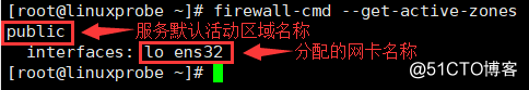
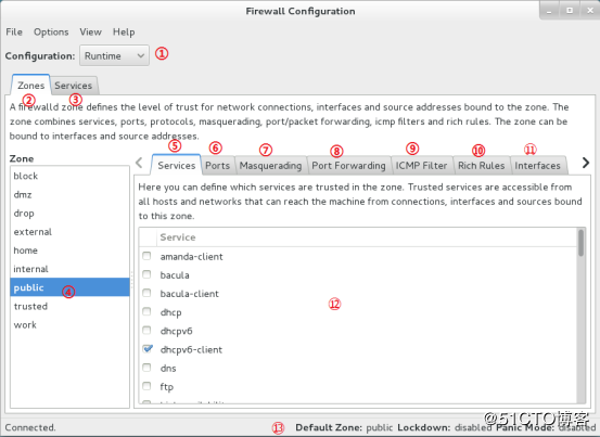
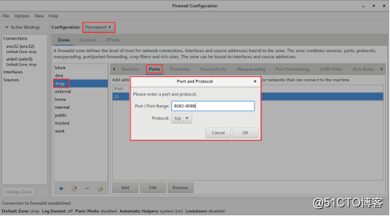
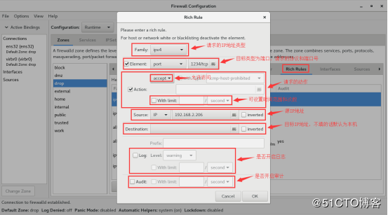
Firewalld provides a dynamically managed firewall with support for network/firewall zones to define the trust level of network connections or interfaces. It has support for IPv4, IPv6 firewall settings and for ethernet bridges and has a separation of runtime and permanent configuration options. It also supports an interface for services or applications to add firewall rules directly.

基本概念

区域

表1:firewalld中常用的区域名称及策略规则

区域(zone) 默认策略规则
trusted 允许所有的数据包进出
home 拒绝进入的流量,除非与出去的流量相关;而如果流量与ssh、mdns、ipp-client、amba-client与dhcpv6-client服务相关,则允许进入
Internal 等同于home区域
work 拒绝进入的流量,除非与出去的流量相关;而如果流量与ssh、ipp-client与dhcpv6-client服务相关,则允许进入
public 拒绝进入的流量,除非与出去的流量相关;而如果流量与ssh、dhcpv6-client服务相关,则允许进入
external 拒绝进入的流量,除非与出去的流量相关;而如果流量与ssh服务相关,则允许进入
dmz 拒绝进入的流量,除非与出去的流量相关;而如果流量与ssh服务相关,则允许进入
block 拒绝进入的流量,除非与出去的流量相关
drop 拒绝进入的流量,除非与出去的流量相关

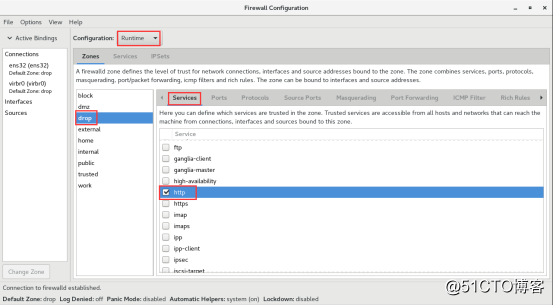
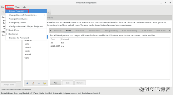
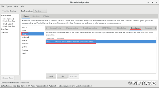
These are the zones provided by firewalld sorted according to the default trust level of the zones from untrusted to trusted:

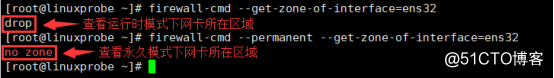
drop : Any incoming network packets are dropped, there is no reply. Only outgoing network connections are possible.

block : Any incoming network connections are rejected with an icmp-host-prohibited message for IPv4 and icmp6-adm-prohibited for IPv6. Only network connections initiated within this system are possible.

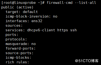
public : For use in public areas. You do not trust the other computers on networks to not harm your computer. Only selected incoming connections are accepted.

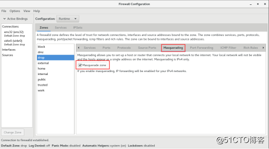
external : For use on external networks with masquerading enabled especially for routers. You do not trust the other computers on networks to not harm your computer. Only selected incoming connections are accepted.

dmz : For computers in your demilitarized zone that are publicly-accessible with limited access to your internal network. Only selected incoming connections are accepted.

work : For use in work areas. You mostly trust the other computers on networks to not harm your computer. Only selected incoming connections are accepted.

home : For use in home areas. You mostly trust the other computers on networks to not harm your computer. Only selected incoming connections are accepted.

internal : For use on internal networks. You mostly trust the other computers on the networks to not harm your computer. Only selected incoming connections are accepted.

trusted : All network connections are accepted.

动静态更新技术之间的区别:iptables每一个更改都需要先清除所有旧有的规则,然后重新加载所有的规则(包括新的和修改后的规则);而firewalld任何规则的变更都不需要对整个防火墙规则重新加载

配置

firewalld服务的主配置文件是firewalld.conf,防火墙策略的配置文件是以xml格式为主,存放在以下两个目录里。

1
2
/etc/firewalld   # 用户配置文件
/usr/lib/firewalld #系统配置文件,预定义配置文件

firewalld有基于CLI(命令行界面)和基于GUI(图形用户界面)两种管理方式,即:firewall-cmd(终端管理工具)和firewall-config(图形管理工具)。

firewalld的参数一般都是以“长格式”来提供的,但是在RHEL7系统里支持部分命令的参数补齐,其中就包括firewall-cmd命令,也就是说可以用Tab键来补齐长格式参数,很酷吧。

命令

表2:firewall-cmd命令中使用的参数以及作用

参数 作用
--get-default-zone 查访默认的区域名称
--set-default-zone=<区域名称> 设置默认的区域,使其永久生效
--get-zones 显示可用的区域
--get-services 显示预定义的服务
--get-active-zones 显示当前正在使用的区域、来源地址和网卡名称
--add-source= 将源自此IP或子网的流量导向指定的区域
--remove-source= 不再将源自此IP或子网的流量导向这个区域
--add-interface=<网卡名称> 将源自该网卡的所有流量都导向某个指定区域
--change-interface=<网卡名称> 将某个网卡与区域进行关联
--list-all 显示当前区域的网卡配置参数、资源、端口以及服务等信息
--list-all-zones 显示所有区域的网卡配置参数、资源、端口以及服务等信息
--add-service=<服务名> 设置默认区域允许该服务的流量
--add-port=<端口号/协议> 设置默认区域允许该端口的流量
--remove-service=<服务名> 设置默认区域不再允许该服务的流量
--remove-port=<端口号/协议> 设置默认区域不再允许该端口的流量
--reload 让“永久生效”的配置规则立即生效,并覆盖当前的配置规则
--panic-on 开启应急状况模式
--panic-off 关闭应急状况模式

firewalld配置的防火墙策略默认为运行时(Runtime)模式,又称为当前生效模式,而且随着系统的重启会失效。如果想让配置策略一直存在,就需要使用永久(Permanent)模式了,方法就是在firewall-cmd命令后面添加--permanent参数,这样配置的防火墙策略就可以永久生效了。但是,永久生效模式有一个“不近人情”的特点,就是使用它设置的策略只有在系统重启后才会生效。如果想让配置的永久策略立即生效,需要手动执行firewall-cmd --reload命令。

注:remove掉ssh服务或者ssh端口,当前远程登陆会话不会断开,退出后就无法远程连接了。

firewalld服务启动、重启、停止

1
2
3
systemctl start firewalld
systemctl restart firewalld
systemctl stop firewalld

重新加载防火墙配置 firewall-cmd --reload

查看firewalld的运行状态 firewall-cmd --state

查看默认当前使用的区域 firewall-cmd --get-default-zone

查看系统默认活动区域名称、来源地址和关联的网卡 firewall-cmd --get-active-zones

firewalld防火墙详解

查看所有可用区域 firewall-cmd --get-zones

查看区域的所有设置

1
2
firewall-cmd --zone=internal --list-all   
firewall-cmd --list-all
firewalld防火墙详解

Target:目标 icmp-block-inversion:ICMP协议类型黑白名单开关(yes/no) Interfaces:关联的网卡接口 sources:来源,可以是IP地址,也可以是mac地址 services:允许的服务 ports:允许的目标端口,即本地开放的端口 protocols:允许通过的协议 masquerade:是否允许伪装(yes/no),可改写来源IP地址及mac地址 forward-ports:允许转发的端口 source-ports:允许的来源端口 icmp-blocks:可添加ICMP类型,当icmp-block-inversion为no时,这些ICMP类型被拒绝;当icmp-block-inversion为yes时,这些ICMP类型被允许。 rich rules:富规则,即更细致、更详细的防火墙规则策略,它的优先级在所有的防火墙策略中也是最高的。

开始

查看所有预设的服务 firewall-cmd --get-services 此时将会列出/usr/lib/firewalld/services/目录中所有的服务名称。

查看所有区域的设置 firewall-cmd --list-all-zones

查看指定网卡所在的区域 firewall-cmd --get-zone-of-interface=ens32

把firewalld的当前默认区域设置为drop,此为永久设置 firewall-cmd --set-default-zone=drop

把ens32网卡关联的区域修改为drop

1
2
firewall-cmd --permanent --zone=drop --change-interface=ens32   # 永久设置
firewall-cmd --zone=drop --change-interface=ens32 # 当前生效
firewalld防火墙详解

我们后面的设置命令将全部使用运行时模式,即当前生效模式。 将来自ens33网卡的流量都作用到默认的drop区域

1
2
3
firewall-cmd --zone=drop -add-interface=ens33   # 作用在指定区域
firewall-cmd -add-interface=ens33 # 作用在默认区域
firewall-cmd -remove-interface=ens33 # 禁止ens33网卡作用在drop区域

注:不指定--zone参数的话,将会对默认区域进行设置 启动关闭firewalld防火墙服务的应急状况模式,远程连接服务器时请慎用

1
2
3
firewall-cmd --panic-on  
firewall-cmd --panic-off
firewall-cmd --query-panic

设置一个来源地址作用在drop区域上面

1
2
3
firewall-cmd --zone=drop --add-source=192.168.1.12  # 作用在指定区域
firewall-cmd --add-source=192.168.1.12 # 作用在默认区域
firewall-cmd --remove-source=192.168.1.12 # 取消源IP为192.168.1.12的包作用在drop区域

说明:凡是IP为192.168.1.12发来包将会使用drop区域设置的规则

对于一个接收到的请求具体使用哪个zone,firewalld是通过三种方式来判断的:

1、source,来源地址 2、Interface,接收请求的网卡 3、firewalld配置的默认区域(zone)

这三个方式的优先级按顺序依次降低,也就是说如果按照source可以找到就不会再按interface去找,如果前两个都找不到才会使用第三个默认区域。 查询drop区域是否允许请求ssh和https服务的流量

常用命令

在drop区域开放https服务 firewall-cmd --zone=drop --add-service=https

取消开放https服务,即禁止https服务 firewall-cmd --zone=drop --remove-service=https

开放22端口 firewall-cmd --zone=drop --add-port=22/tcp

取消开放22端口 firewall-cmd --zone=drop --remove-port=22/tcp

开放8080和8081端口 firewall-cmd --zone=drop --add-port=8080-8081/tcp

查询drop区域开放了哪些端口 firewall-cmd --zone=drop --list-ports

允许icmp协议流量,即允许ping firewall-cmd --zone=drop --add-protocol=icmp

取消允许icmp协议的流量,即禁ping firewall-cmd --zone=drop --remove-protocol=icmp

查询drop区域开放了哪些协议 firewall-cmd --zone=drop --list-protocols

端口转发

将原本访问本机888端口的流量转发到本机22端口 firewall-cmd --zone=drop --add-forward-port=port=888:proto=tcp:toport=22

将原本访问本机888端口的流量转发到ip为192.168.2.208的主机的22端口,需要开启masquerade

1
2
firewall-cmd --zone=drop --add-masquerade
firewall-cmd --zone=drop --add-forward-port=port=888:proto=tcp:toport=22:toaddr=192.168.2.208

测试端口转发功能是否生效 在客户端尝试访问192.168.2.210主机的888端口,连上去后发现实际连接的是192.168.2.208主机,测试OK。

firewalld防火墙详解
firewalld防火墙详解

富规则

接下来我们来看富规则的设置,即 rich rules

允许192.168.2.208主机的所有流量 firewall-cmd --zone=drop --add-rich-rule="rule family="ipv4" source address="192.168.2.208" accept"

允许192.168.2.208主机的icmp协议,即允许192.168.2.208主机ping firewall-cmd --add-rich-rule="rule family="ipv4" source address="192.168.2.208" protocol value="icmp" accept"

取消允许192.168.2.208主机的所有流量 firewall-cmd --zone=drop --remove-rich-rule="rule family="ipv4" source address="192.168.2.208" accept"

允许192.168.2.208主机访问ssh服务 firewall-cmd --zone=drop --add-rich-rule="rule family="ipv4" source address="192.168.2.208" service name="ssh" accept"

禁止192.168.2.208访问https服务,并返回错误信息 firewall-cmd --zone=drop --add-rich-rule="rule family="ipv4" source address="192.168.2.208" service name="https" reject" 注:如果是drop的话是直接丢弃,会返回timeout(连接超时)

允许192.168.2.0/24网段的主机访问22端口 firewall-cmd --zone=drop --add-rich-rule="rule family="ipv4" source address="192.168.2.0/24" port protocol="tcp" port="22" accept"

每分钟允许2个新连接访问ftp服务 firewall-cmd --add-rich-rule="rule service name=ftp limit value=2/m accept"

允许新的ipv4和ipv6连接ftp,并使用日志和审核,每分钟允许访问一次 firewall-cmd --add-rich-rule="rule service name=ftp log limit value="1/m" audit accept"

拒绝来自192.168.2.0/24网段的连接,10秒后自动取消 firewall-cmd --add-rich-rule="rule family=ipv4 source address=192.168.2.0/24 reject" --timeout=10

允许ipv6地址为2001:db8::/64子网的主机访问dns服务,并且每小时审核一次,300秒后自动取消 firewall-cmd --add-rich-rule="rule family=ipv6 source address="2001:db8::/64" service name="dns" audit limit value="1/h" reject" --timeout=300

将来自192.168.2.0/24网段访问本机80端口的流量转发到本机的22端口 firewall-cmd --zone=drop --add-rich-rule="rule family=ipv4 source address=192.168.2.0/24 forward-port port=80 protocol=tcp to-port=22"

将来自192.168.2.0/24网段访问本地80端口的流量转发到192.168.2.208主机的22端口 firewall-cmd --zone=drop --add-rich-rule="rule family=ipv4 source address=192.168.2.0/24 forward-port port=80 protocol=tcp to-port=22 to-addr=192.168.2.208"

伪装,将来自局域网192.168.2.0/24网段访问外网的流量映射为网络出口公网IP,即修改源IP地址

1
2
firewall-cmd --zone=drop --add-masquerade
firewall-cmd --zone=drop --add-rich-rule="rule family=ipv4 source address=192.168.2.0/24 masquerade"

好了,写的差不多了,工作中基本上够用了

GUI配置

在RHEL7之前的发行版本默认的防火墙中,几乎没有图形化的防火墙管理工具,但是firewalld却有,firewall-config是firewalld防火墙配置管理工具的GUI(图开用户界面)版本,几乎可以实现所有命令行执行的操作。即使没有扎实的Linux命令基础,也完合可以通过它来妥善配置firewalld防火墙策略。Firewall-config的界面如下图所示,功能具体如下:

firewalld防火墙详解

1、选择运行时(Runtime)模式或永久(Permanent)模式。 2、可选的策略集合区域列表。 3、常用的系统服务列表。 4、当前正在使用的区域。 5、管理当前被选中区域中的服务。 6、管理当前被选中区域中的端口。 7、开启或关闭SNAT(源地址转换协议)技术。 8、设置端口转发策略。 9、控制请求icmp服务的流量。 10、管理防火墙的富规则。 11、管理网卡设备。 12、被选中区域的服务,若勾选了相应服务前面的复选框,则表示允许与之相关的流量。 13、Firewall-config工具的运行状态。

对外开放http服务,如下图

firewalld防火墙详解

添加一条防火墙规则,使其放行访问8080-8088端口(TCP协议)的流量,并且永久生效

firewalld防火墙详解

单击Options菜单中的Reload Firewalld选项,让上面配置的永久规则立即生效,这与在命令行中执行--reload参数的效果一样。

firewalld防火墙详解

SNAT技术相信很多人都知道,那现在我们来开启SNAT技术,其实就是命令行下的masquerade。

firewalld防火墙详解

下面我们来配置一个端口转发规则,将888端口的流量转发到其他主机的22端口上。 注:转发本机端口不需要开启masquerade,转发到别的主机才需要开启masquerade。

firewalld防火墙详解

配置富规则,允许192.168.2.206主机访问本机的1234端口号

firewalld防火墙详解

最后来看一下区域和网卡的关联,增加网卡的话只需要输入网卡名称即可。

firewalld防火墙详解

下面是我自己写的一个简单的防火墙初始化脚本,5210是ssh端口号,192.168.2.208是保垒机,192.168.2.206是备用ssh机器

1
2
3
4
5
6
7
8
9
10
11
12
systemctl stop firewalld
\cp -p /usr/lib/firewalld/zones/drop.xml /etc/firewalld/zones/
systemctl start firewalld
firewall-cmd --set-default-zone=drop
firewall-cmd --permanent --zone=drop --change-interface=ens32
firewall-cmd --permanent --zone=drop --add-service=https
firewall-cmd --permanent --zone=drop --add-protocol=icmp
firewall-cmd --permanent --zone=drop --add-masquerade
firewall-cmd --permanent --zone=drop --add-rich-rule="rule family="ipv4" source address="192.168.2.208" port protocol="tcp" port="5210" accept"
firewall-cmd --permanent --zone=drop --add-rich-rule="rule family="ipv4" source address="192.168.2.206" port protocol="tcp" port="5210" accept"
firewall-cmd --permanent --zone=drop --add-rich-rule="rule family="ipv4" source address="116.226.230.115" port protocol="tcp" port="8023" accept"
firewall-cmd --reload

firewalld.org

Enable and Disable firewalld

firewalld provides an init script for systems using classic SysVinit and also a systemd service file. The following documentation is about the systemd service used in Fedora, RHEL and CentOS distributions.

It is not recommended to use iptables directly while firewalld is running as this could lead into some unexpected issues. If a user, for example, is removing base rules or chains of the chain structure, then a firewalld reload might be needed to create them again.

Install and enable firewalld

If the iptables, ip6tables, ebtables and ipset services are in use:

1
2
3
4
5
6
7
systemctl disable --now iptables.service
systemctl disable --now ip6tables.service
systemctl disable --now etables.service
systemctl disable --now ipset.service
dnf install firewalld firewall-config firewall-applet
systemctl unmask --now firewalld.service
systemctl enable --now firewalld.service

To check the firewall state you have different options. The fist option is to use systemctl status firewalld the other one is to use firewall-cmd --state.

The output of the systemctl command should look like this:

1
2
3
4
5
6
7
8
9
$ systemctl status firewalld
● firewalld.service - firewalld - dynamic firewall daemon
Loaded: loaded (/usr/lib/systemd/system/firewalld.service; enabled; vendor pr
Active: active (running) since Wed 2016-06-29 14:28:51 CEST; 1 weeks 6 days a
Docs: man:firewalld(1)
Main PID: 24540 (firewalld)
Tasks: 2 (limit: 512)
CGroup: /system.slice/firewalld.service
└─24540 /usr/bin/python3 -Es /usr/sbin/firewalld --nofork --nopid

The output of the firewall-cmd command should look like this:

1
2
$ firewall-cmd --state
running

Install and enable iptables, ip6tables, ebtables and ipset services

If firewalld is enabled and you want to enable the iptables, ip6tables, ebtables and ipset services instead:

1
2
3
4
5
6
dnf install iptables-services ebtables ipset-service
systemctl mask --now firewalld.service
systemctl enable --now iptables.service
systemctl enable --now ip6tables.service
systemctl enable --now etables.service
systemctl enable --now ipset.service

The use of the mask line is recommended as systemd will start firewalld if there is another service requires it or if the D-Bus interface of firewalld is used. If the service only gets disabled, then it will not be auto started anymore.

jianshu.com

ssh 提供两种级别的安全认证:

  1. 基于口令的安全认证
  2. 基于密钥的安全认证

基于口令的安全认证

需要知道用户名和密码即可登录,该连接是加密的,但客户端不能确认目标主机是否为“伪造的”,也不能保证口令安全。

远程主机的 /etc/ssh/sshd_config 需配置:

1
PasswordAuthentication yes

重启 sshd 使改动生效:

1
$ /etc/init.d/sshd reload

基于密钥的安全认证

需要用户持有“公钥/私钥对”,远程服务器持有公钥,本地持有私钥。

客户端向服务器发出请求。服务器收到请求之后,先在用户的主目录下找到该用户的公钥,然后对比用户发送过来的公钥。如果一致,服务器用公钥加密“质询”并发送给客户端。客户端收到“质询”后用私钥解密,再发还给服务器。认证结束。

生成 ssh-key,选加密算法(rsa、dsa),给秘钥命名(可选):

1
$ ssh-keygen -t rsa -C "name"

passphrase 是证书口令,以加强安全性,避免证书被恶意复制。

会在 ~.ssh 下生成 id_rsa, id_rsa.pub 两个文件,分别是 私钥/公钥。

公钥需保存到远程服务器 ~/.ssh/authorized_keys 里,私钥由客户端本地留存。

要保证 .sshauthorized_keys 都只有用户自己有写权限。否则验证无效。

1
2
$ chmod -R 700 ~/.ssh/
$ chmod 600 ~/.ssh/authorized_keys

ssh 配置的一些实践

1
2
3
4
5
6
7
8
9
10
11
12
13
14
15
$ vim /etc/ssh/sshd_config


PermitRootLogin no


StrictModes no


RSAAuthentication yes
PubkeyAuthentication yes
AuthorizedKeysFile %h/.ssh/authorized_keys


PasswordAuthentication no

持有多个 ssh-key 时的使用方法

简单情况下,通过手动指定私钥文件登录

1
$ ssh username@hostname -i ~/.ssh/my_id_rsa

觉得麻烦可以配置客户端的 /etc/ssh/ssh_config

1
2
3
IdentityFile ~/.ssh/id_rsa

IdentityFile ~/.ssh/my_id_rsa

你也可以使用 SSH Agent,下面以使用 GitHub 为场景简单介绍。

1
2
$ ssh-keygen -t rsa -C 'second@mail.com'
$ ssh-add ~/.ssh/id_rsa_second

创建 ~/.ssh/config

1
2
3
4
5
6
7
8
9
10
Host github.com
HostName github.com
User git
IdentityFile C:/Users/username/.ssh/id_rsa


Host github-second
HostName github.com
User git
IdentityFile C:/Users/username/.ssh/id_rsa_second

配置完成后,在连接非默认账号的仓库时,远端地址要修改为

1
git remote add test git@github-second:second/test.git

数据库入门

数据库相关从业

前面五种:重点是设计和应用,侧重于软件和数据逻辑层面。

数据库应用开发 (application development) > 除了基本的SQL方面的知识,还要对开发流程,软件工程,各种框架和开发工具等等 > 数据库应用开发这个方向上的机会最多,职位最多

数据建模专家 (data modeler) > 除了基本的SQL方面的知识,非常熟悉数据库原理,数据建模 > 负责将用户对数据的需求转化为数据库物理设计和物理设计 > 这个方向上在大公司(金融,保险,研究,软件开发商等)有专门职位, > 在中小公司则可能由程序员承担。

商业智能专家 (business intelligence - BI) > 主要从商业应用,最终用户的角度去从数据中获得有用的信息, > 涉及OLAP (online analytical processing) > 需要使用SSRS, cognos, crystal report等报表工具,或者其他一些数据挖掘,统计方面的软件工具

ETL开发 (ETL Developer) > 使用ETL工具或者自己编写程序在不同的数据源之间对数据进行导入,导出,转换, > 所接触的数据库一般数据量非常大,要求进行的数据转换也比较复杂。 > 和数据仓库和商业智能的关系比较密切。

在一些数据库应用规模很大的公司里面有专门的职位, 中小公司里面则可能由程序员或者DBA负责这方面的工作。

数据构架师 (Data Architect) > 主要从全局上制定和控制关于数据库在逻辑这一层的大方向, > 也包括数据可用性,扩展性等长期性战略, > 协调数据库的应用开发,建模,DBA之间的工作。 > 这个方向上在大公司(金融,保险,研究,软件开发商等)有专门职位, > 在中小公司或者没有这个职位,或者由开发人员,DBA负责。

后面五种:重点是运营和维护,侧重与硬件和数据物理层面。

数据库管理员 (database administrator - DBA) > 数据库的安装,配置,调优,备份/恢复,监控,自动化等, > 协助应用开发(有些职位还要求优化SQL,写存储过程和函数等) > 这个方向上的职位相对少一些,但一般有点规模的公司还是会有这样的职位

数据仓库专家 (data warehouse - DW) > 应付超大规模的数据,历史数据的存储,管理和使用, > 和商业智能关系密切,很多时候BI和DW是放在一个大类里面的, > 但是我觉得DW更侧重于硬件和物理层上的管理和优化。

存储工程师 (storage engineer) > 专门负责提供数据存储方案,使用各种存储技术满足数据访问和存储需求, > 和DBA的工作关系比较密切。 > 对高可用性有严格要求(比如通信,金融,数据中心等)的公司通常有这种职位, > 这种职位也非常少。

性能优化工程师 (performance engineer) > 专长数据库的性能调试和优化,为用户提供解决性能瓶颈方面的问题。 > 我知道至少IBM, 微软和Oracle都有专门的数据库性能实验室(database performance lab), > 也有专门的性能优化工程师,负责为其数据库产品和关键应用提供这方面的技术支持。 > 对数据库性能有严格要求的公司(比如金融行业)可能会有这种职位。 > 因为针对性很强,甚至要求对多种数据库非常熟悉,所以职位极少。

高级数据库管理员 (senior DBA) > 在DBA的基础上,还涉及上面3种职位的部分工作,具体包括下面这些: > 对应用系统的数据(布局,访问模式,增长模式,存储要求等)比较熟悉。 > 对性能优化非常熟悉,可以发现并优化从SQL到硬件I/O,网络等各个层面上的瓶颈 > 对于存储技术相对熟悉,可能代替存储工程师的一些工作, > 对数据库的高可用性技术非常熟悉(比如MSSQL的集群,ORACLE RAC/FailSafe, IBM的DPF, HADR等) > 对大规模数据库有效进行物理扩展(比如表分区)或者逻辑扩展(比如数据库分区,联合数据库等) > 熟悉各种数据复制技术,比如单向,双向,点对点复制技术,以满足应用要求。 > 灾难数据恢复过程的建立,测试和执行 > 这种职位一般只在对数据库要求非常高并且规模非常大(比如金融,电信,数据中心等)的公司需要, > 而且这种公司一般有一个专门独立负责数据库的部门或组。

关系型数据库

说到关系型数据库,不仅仅是涉及计算机概念,也涉及一些数学概念,例如表格的概念、包含关系、关系运算及关系代数等。

关系模型术语

image-20210512085059008

  1. :关系型数据库由表集合而成,表是关系型数据库的一个基本组成,每个表具有唯一的名字。
  2. 关系:在关系型数据库中,关系 指代 的概念,即一般可认为 关系 = 表
  3. 元组:在关系型数据库中,元组 指代 的概念,即一般可认为 元组 = 行
  4. 属性:在关系型数据库中,属性 指代 的概念,即一般可认为 属性 = 列
  5. :属性下所有元素的可取值范围或取值类型。
  6. 原子域:域中的元素不可再分,则称为原子域。
  7. 空值:属性下元素为空(NULL)。
  8. 关系实例:即表实例,严谨说法是 “表示一个关系的特定实例,也就是所包含的一组特定的行”,就是不仅仅只有属性这一行,还具有特定的某些具体数据的表格。
  9. 关系模式:即表模式,严谨说法是“关系模式由属性序列及各属性对应域组成”,通俗地说就是,没有具体数据,而仅定义了属性和域的表格。
  10. 数据库模式:对数据库的逻辑设计。
  11. 数据库实例:对数据库中数据的快照。
  12. 超码:是一个或多个属性的集合,超码内的一个或多个属性组合可以唯一区分和标识一个元组。
  13. 候选码:最小超码。
  14. 主码:主码是候选码的一种,最重要的是,主码由设计者选中,具有人为性
  15. 外码:用于表示关系之间的引用和被引用关系。即关系A中的某项属性来自于关系B中的某项属性,则称该引用过来的属性为外码。但据课本,是被引用的主码称为外码。
  16. image-20210512134116409

结构化查询语言SQL

发展历史

image-20210512192241572

数据库必知词汇:SQL标准

SQL标准是由国际标准化组织(ISO)、美国国家标准委员会ANSI等制定的,对数据库管理系统的统一操作方式。

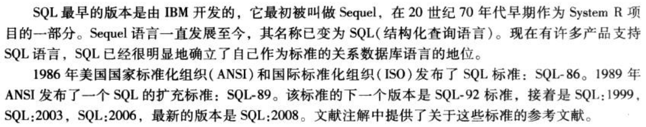
SQL 是 Structured Query Language 的缩写,规范的发音是 “ˌɛsˌkjuːˈɛl”。但是它的前身是著名的关系数据库原型系统 System R 所采用的 SEQUEL 语言,这也是为什么有很多人将其读作 “ˈsiːkwəl” 的来源。也有人类比 GNU 这个词的定义(GNU’s Not UNIX),认为 SQL 是 SQL Query Language 的缩写。

IBM对关系数据库以及SQL语言的形成和规范化产生了重大的影响,第一个版本的SQL标准SQL86就是基于System R的手册而来的。Oracle在1979年率先推出了支持SQL的商用产品。随着数据库技术和应用的发展,为不同RDBMS提供一致的语言成了一种现实需要。

对SQL标准影响最大的机构自然是那些著名的数据库产商,而具体的制订者则是一些非营利机构,例如国际标准化组织ISO、美国国家标准委员会ANSI等。各国通常会按照ISO标准和ANSI标准制定自己的国家标准。

“美国国家标准化组织(ANSI)”是一个核准多种行业标准的组织。SQL作为关系型数据库所使用的标准语言,最初是基于IBM的实现在1986年被批准的。1987年,“国际标准化组织(ISO)”把ANSI SQL作为国际标准。

SQL发展的简要历史: 1986年,ANSI X3.135-1986,ISO/IEC 9075:1986,SQL-86 1989年,ANSI X3.135-1989,ISO/IEC 9075:1989,SQL-89 1992年,ANSI X3.135-1992,ISO/IEC 9075:1992,SQL-92(SQL2) 1999年,ISO/IEC 9075:1999,SQL:1999(SQL3) 2003年,ISO/IEC 9075:2003,SQL:2003 2008年,ISO/IEC 9075:2008,SQL:2008 2011年,ISO/IEC 9075:2011,SQL:2011 补充 1986 年,ANSI X3.135-1986,ISO/IEC 9075:1986,SQL-86。这是 ANSI 首次将 SQL 语言标准化的版本。 1989 年,ANSI X3.135-1989,ISO/IEC 9075:1989,SQL-89。增加了完整性约束。 1992 年,ANSI X3.135-1992,ISO/IEC 9075:1992,SQL-92(SQL2)。最重要的一个版本。 引入了标准的分级概念。 1999 年,ISO/IEC 9075:1999,SQL:1999(SQL3)。变动最大的一个版本。改变了标准符合程度的定义;增加了面向对象特性、正则表达式、存储过程、Java 等支持。 2003 年,ISO/IEC 9075:2003,SQL:2003。引入了 XML、Window 函数等。 2008 年,ISO/IEC 9075:2008,SQL:2008。引入了 TRUNCATE 等。 2011 年,ISO/IEC 9075:2011,SQL:2011。引入了时序数据等。 2016 年,ISO/IEC 9075:2016,SQL:2016。引入了 JSON 等。

绝大多数人提起SQL标准,涉及的内容其实是SQL92里头最基本或者说最核心的一部分。SQL92本身是分级的,包括入门级、过度级、中间级和完全级,推荐泛读SQL92,增量式式阅读其他标准。而随着SQL标准的发展,其包含的内容实在太多了,而且有很多特性对新的SQL产品而言也越来越不重要了。从SQL99之后,标准中符合程度的定义就不再分级,而是改成了核心兼容性和特性兼容性;也没有机构来推出权威的SQL标准符合程度的测试认证了。

作用

  1. 数据库查询
  2. 定义数据结构
  3. 修改数据
  4. 说明安全性约束条件

基本数据类型

image-20210512192708528

以上所有类型都可能包含一个被称作空值的特殊值。NULL表示一个缺失的值,即表示该值可能存在但并不为人所知,或者可能根本不存在。

关于char / varchar / nvarchar的比较

image-20210512193208247

SQL完整性约束

image-20210512201050138

例如,上方教员的名称为 “张三”, 我想删除后保存,会破坏 instructor 关系下 name 的非空约束,SQL不通过这种操作。

数据库操作

新建表格

数据表格新建格式及样例如下:

image-20210512193506987

其中r是关系名,即表名;Ax是属性名,即列名;Dx是属性的域,即指定了A的类型及可选约束,用于限制所允许的Ax取值的集合。

1
2
3
4
5
6
7
8
9
10
11
12
13
14
15
16
17
18
19
20
21
22
23
24
25
26
27
28
29
30
31
32
33
34
35
36
37
38
39
40
41
42
43
44
45
46
47
48
49
50
51
52
/*部门关系*/
create table department(
dept_name varchar(20),
building varchar(15),
budget numeric(12,2),
primary key(dept_name)
);

/*课程关系*/
create table course(
coourse_id varchar(7),
title varchar(50),
dept_name varchar(20),
credits numeric(2,0),
primary key(course_id),
foreign key (dept_name) references department
);

/*教员关系*/
create table instructor(
ID varchar(5),
name varchar(20) not null,
dept_name varchar(20),
salary numeric(8,2),
primary key(ID),
foreign key(dept_name) references department
);

/*(课程)章节关系*/
create table section(
course_id varchar(8),
sec_id varchar(8),
semester varchar(6),
year numeric(4,0),
building varchar(7),
time_slot_id varchar(4),
primary key(course_id, sec_id, semester, year),
foreign key(course_id) references course
);

/*教师关系*/
create table teachers(
ID varchar(5),
course_id varchar(8),
sec_id varchar(8),
semester varchar(6),
year numeric(4,0),
primary key(ID, course_id, sec_id, semester, year),
foreign key(course_id, sec_id, semester, year) references section,
foreign key(ID) references instructor
);

foreign key 可以拿来当 primary key,如章节关系中所示。

not null 关键字约束表明 “在该属性上不允许空值” 。

插入

image-20210512201338050

插入值过程中,所给出的值的顺序应与关系模式中的属性顺序一致。

删除

delete 命令可以用于删除元组。

  • 如果直接使用命令 delete from student , 则将从 student 关系中删除所有元组。
  • 使用其他语句可以执行特定删除,如:
    • 使用命令 delete from instructor where salary between 13000 and 150000; ,删除所有工资在13000到15000美元之间的教师
    • 其他操作……

丢弃表格