关于博客更新
博客已转移至 isletspace.flowus.cn
后续更新将会在 flowus上进行
博客已转移至 isletspace.flowus.cn
后续更新将会在 flowus上进行
| 传电方式 | 理论传电距离 | 输电功率 | 原理 | 缺点 | 优点 | 市场应用 |
|---|---|---|---|---|---|---|
| 电磁感应耦合 | 厘米级 | 千瓦级 | 供电体与受电体等效成一组可分离的变压器,当供电体中流过高频电流时,受电体会感应出同频电功率。 | 硬件设计难度较低; 传输效率在90%以上; |
无线充电设备 | |
| 非辐射磁共振耦合 | 米级 | 千瓦级 | 其利用两个或多个具有相同谐振频率及高品质因数的电磁系统,通过工作于特定频率的电感及电容的耦合作用产生电磁谐振,高频能量发生大比例交换并被负载吸收。 | 硬件设计成本较高; | 电能传输做损耗较低; | |
| 微波辐射 | 公里级 | / | 将电能转换为微波,利用天线进行发送和接收。 | 无法绕过障碍物; 传输功率小; 损失功率较大时会对生物体造成一定损伤 |
适用于远程传输 |

内核实现了对硬件的管理,为应用软件提供了使用硬件的接口。
以下内容系摘抄整理。
日志的等级由低到高应该是:Debug < Info
< Warn < Error <
Fatal
| DEBUG | INFO | WARN | ERROR | FATAL | |
|---|---|---|---|---|---|
| 严重程度 | 最低 | 一般 | 较高 | 高 | 极高 |
| 严重性说明 | 调试时使用,便于开发者快速地详细地了解系统运行状况。正式发布时会禁用。 | 输出信息以反馈系统运行状态给用户。 | 可修复的潜在错误或不规范的代码、编译条件等。 | 可修复错误。软件无法正常运行。 | 相当严重的错误,可能无法修复。继续运行难以保证。 |
| 使用情况 | 用于打印程序应该出现的正常状态信息, 便于追踪定位。 | 表明系统出现轻微的不合理但不影响运行和使用。 | 表明出现了系统错误和异常,无法正常完成目标操作。 |
错误日志格式大致可以有以下类型。
1 | log.error(“[接口名或操作名] [Some Error Msg] happens. [params] [Probably Because]. [Probably need to do].”); |
或 1
2
3
4
5log.error(“[Some Error Msg] happens to 错误参数或内容 when [in some condition]. [Probably Because]. [Probably need to do].”);
log.error(String.format(“[Some Error Msg] happens to %s when [in some condition]. [Probably Because]. [Probably need to do].”, parameters));
[Probably Reason]. [Probably need to do]. 在某些情况下可以省略; 在一些重要接口和场景下最好能说明一下。
每一条错误日志都是独立的,尽可能完整、具体、直接说明何种场景下发生了什么错误,由什么原因导致,要采用什么措施或步骤。
错误日志是排查问题的重要手段之一。 当我们编程实现一项功能时, 通常会考虑可能发生的各种错误及相应原因:
要排查出相应的原因, 就需要一些关键描述来定位原因。这就会形成三元组:错误现象 -> 错误关键描述 -> 最终的错误原因。
需要针对每一种错误尽可能提供相应的错误关键描述,从而定位到相应的错误原因。也就是说,编程的时候,要仔细思考, 哪些描述是非常有利于定位错误原因的, 尽可能将这些描述添加到错误日志中。
smb 服务可以让多种设备跨平台、跨设备传输、共享文件内容,包括 linux 、mac 、windows、android等。一般开启服务的叫 server,使用服务的叫 client。
注意事项:
下面介绍三个主流PC的smb服务开启流程(仅供参考)。
在debian系linux的配置流程如下:
samba
服务:sudo apt install sambachomd 755 /home/isletspace/sharesmb.conf
文件:sudo vim /etc/samba/smb.conf1 | [share] |
上面的配置信息解释如下:
[share]:smb://xxxx.xxx/share访问时的第二级域名
comment:smb 访问路径说明
browseable:是否可在局域网中可见
writable:是否可写入
read only:是否只可读
create mask:操作权限,普通人访问的就设置0755,如果只有自己用,可以设置0777
valid users:可用用户user01
sudo useradd user01sudo smbpasswd -a user01sudo service smbd restart1 | # 测试是否可以ping通 |
其他命令:
1 | # 查看samba服务器中已拥有哪些用户: |
Mac开启服务大致如文章《Mac 开启局域网smb文件共享》所述。
windows 的流程太复杂,但基本上靠这篇文章《Windows 10/ 11 下安全并正确地使用 SMB 共享》可以搞定
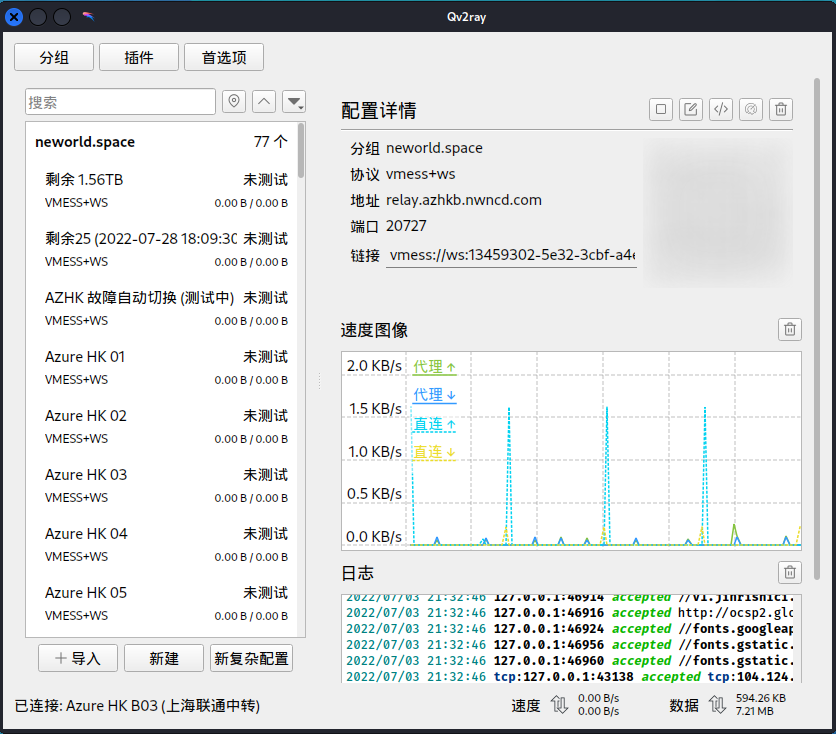
首先要说明的一点,linux 上的 v2ray 分为两部分:
使用QT 制作的 qv2ray GUI界面
v2ray 的运行核心
这两部分需要分别安装和下载。
Github 上的项目路径:https://github.com/v2fly/
GUI 界面的安装可以参考:新手起步
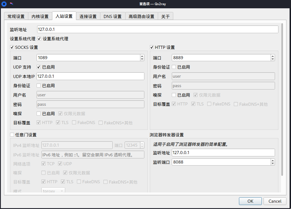
安装、配置完毕之后的使用界面如下。
如果使用 ubuntu 或者 kali 等系统的稳定版本,则可以参考以下命令:
1 | # 安装必要工具 |
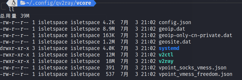
注意:这个一定要和 qv2ray 安装统一个时期的版本,github上有个
pre-release 的 v5.0.7
版本,里面缺少了组件(v2ctl),是不能跟 qv2ray
一起使用的。
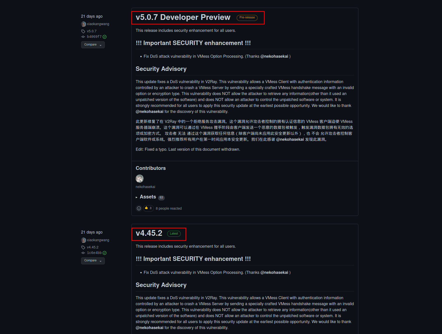
可以参考 neworld.space 的教程《Linux Qv2ray 使用教程》 进行安装。
如果安装版本不正确,会报
v2ray core faied with an exit code: 2 的错误。
设置完之后,还不能马上使用,需要在浏览器中进行代理设置。
例如,火狐浏览器的设置中,找到 “网络代理” 。
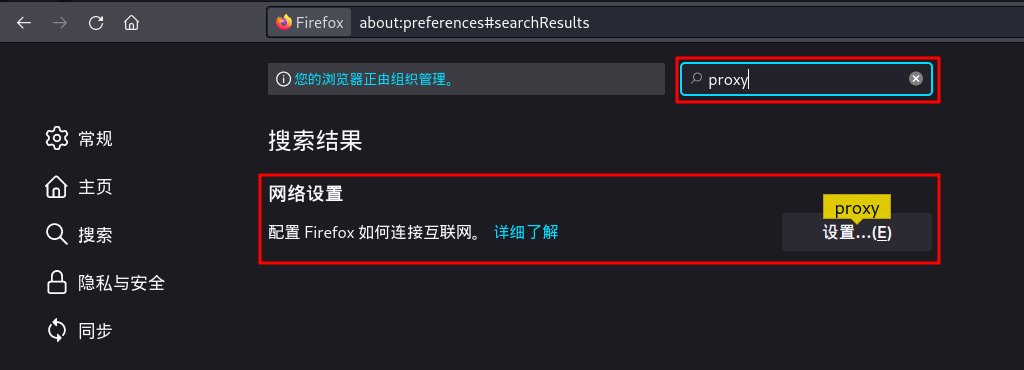
可以选择 “使用系统代理设置” 和 “手动配置代理”两种。
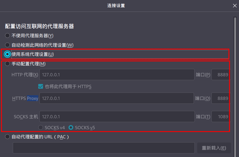
其中手动配置代理就需要对照着 qv2ray 的设置信息来配置即可。
命令行如果需要代理,则需要安装 proxychains
1 | sudo apt install -y proxychians |
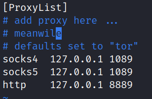
安装完之后用 sudo 权限去配置
/etc/proxychains.conf 文件,将文件最后面的
sock4 127.0.0.1 9095 改成 和 qv2ray 图形配置中的
sock5 一样的配置信息,如 sock5 127.0.0.1 1089
即可。
如果是在mac系统下,则配置文件的路径为 /usr/local/etc
。
如下所示,则是OK的。
使用的时候,直接在命令前面加 proxychains 或者
proxychains4 即可,如:
1 | proxychains ping google.com |
搞定 v2ray 和 proxychains ,下次拉代码再也不痛苦了。
1 | curl -s https://storage.islet.space/08_Script/project/c_init.sh | bash -s -- |
build / src / inc
/ lib / docREADME.md、src/main.c
、CMakeLists.txt.clang-format.gitignore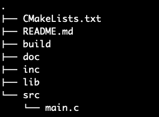
1 | curl -s https://storage.islet.space/08_Script/debian/init.sh | bash -s -- |
zsh 和 ohmyzsh ,并设置
zsh 为默认shellvim / nodejsgcc / lcov /
valgrind / cmake / make /
git / repoandroid-ndk-r20b /
gcc-arm-none-eabi-5.4 /
gcc-arm-none-eabi-10.31 | curl -s https://repo.anaconda.com/miniconda/Miniconda3-latest-Linux-x86_64.sh | bash -s -- |
FTDI 硬件是由 FTDI chip 公司开发的用于高性能 USB 转各种底层通信协议 的芯片。所支持的协议包括 UART / SPI / I2C / JTAG etc. ,还有特殊的 bit-bang 协议。
FT4232 基本上是 FT2232 的升级版,从 2个8bit 独立通道,升级成 4个8bit 独立通道,每个通道都具有独立互不干扰的时钟。
FT4232HL 芯片可以实现 USB 2.0 转换成
四个虚拟通道(VCP,即 Virtual COM
Port) 的功能,该四个虚拟通道可以模拟 UART / JTAG / SPI / I2C
功能,IO口电压为 3.3V 。
本文基于 FT423H 的迷你模块进行开发,该芯片的官方说明如 《FT4232HL》 。
libusb 1.0 - Library for talking to USB devices from user-space. Needed by libftdi. libconfuse - Library for parsing configuration files. Needed by ftdi_eeprom.
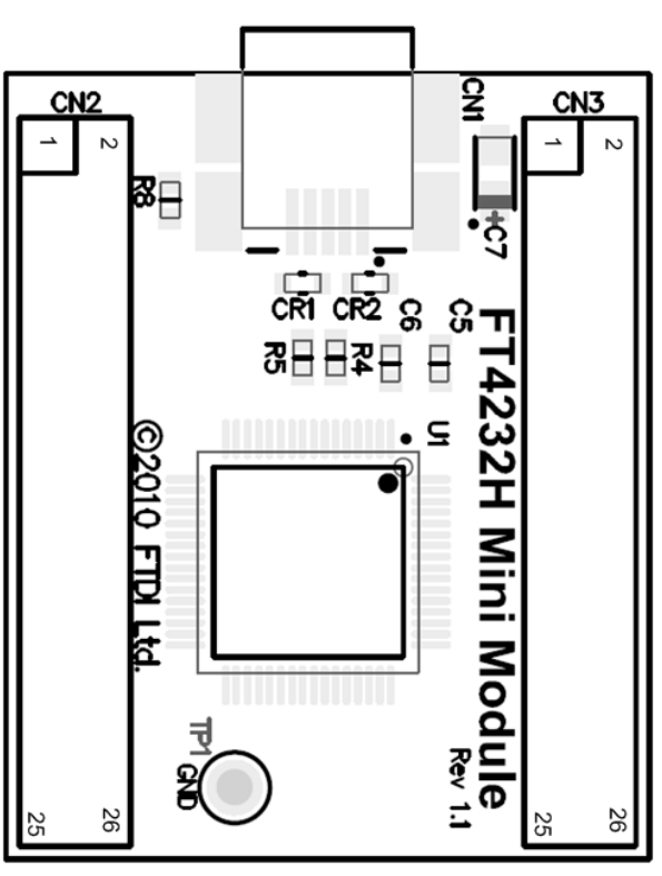
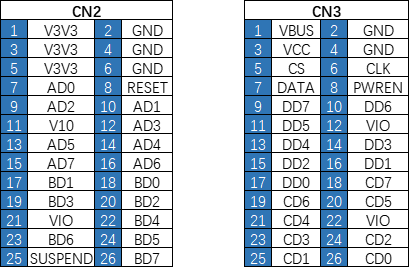
FT4232HL开发板 正面 视图引脚分布:
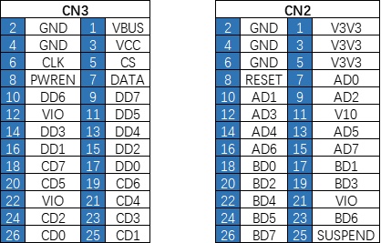
FT4232HL开发板 反面 视图引脚分布:
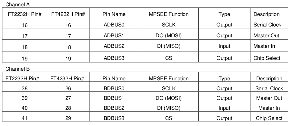
如果使用 libMPSSE 进行 SPI 通信开发,则默认使用下方的通信接口。
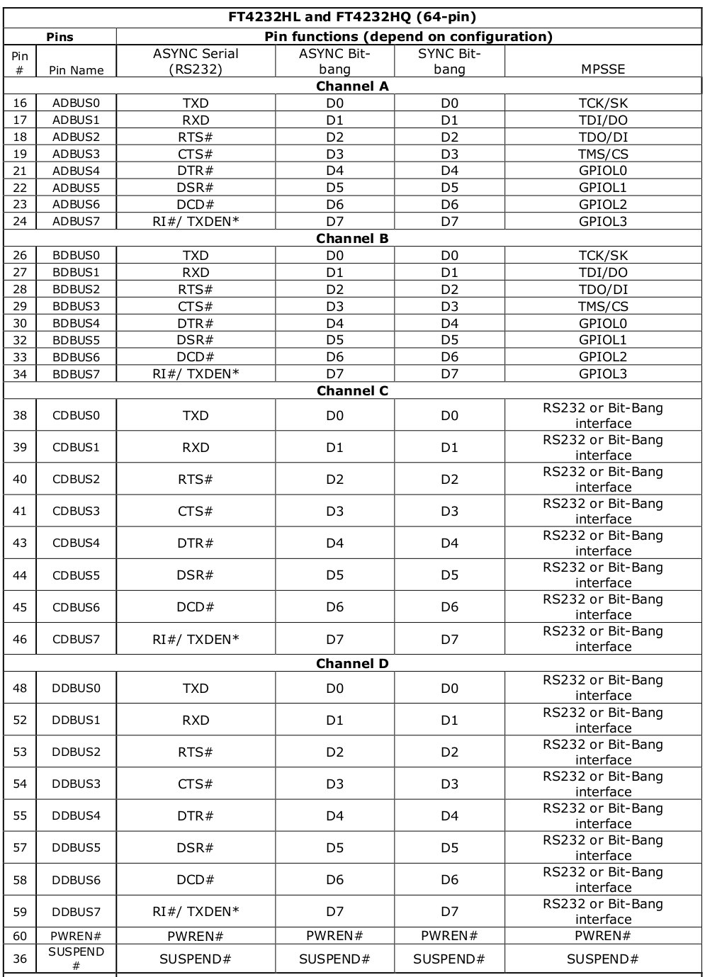
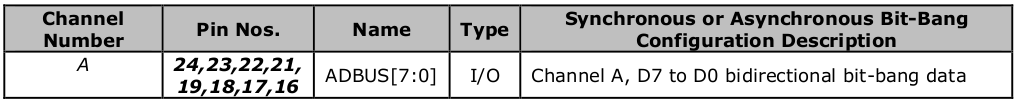
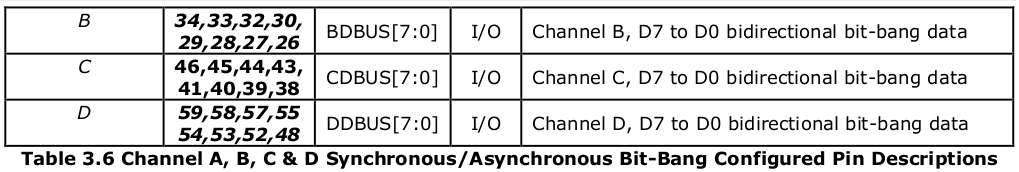
FT4232H的通道 A、B、C 或通道 D 可以被配置为 bit-bang 接口。有两种类型的 bit-bang 模式:同步和异步。
当配置为任何 bit-bang 模式(同步或异步)时,使用的引脚和信号的描述见表3.6
FT4232H 的驱动分为 VCP / D2XXX 和 D3XXX 三个。其中,D3XXX 是适用于 USB 3.0 的,这里不需要安装。
window 版本的驱动安装器就包含了 VCP 和 D2XXX。
驱动安装页面:Virtual COM Port Drivers
官方驱动安装教程:Windows 10/11 Installation Guide
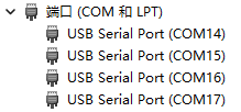
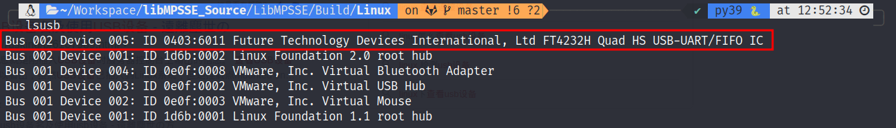
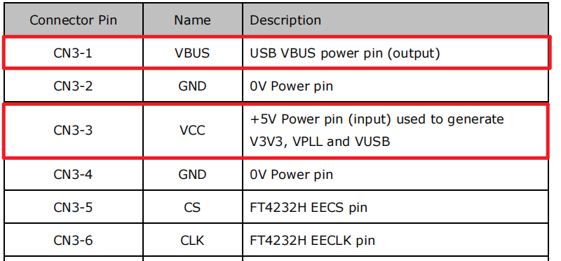
注意:驱动安装完毕之后,PC 不会立即识别
该设备。需要使用 跳线帽,将 CN3 的 1 和 3
口进行短接。让设备供上5V的电。
D2XXX 是针对 FTDI 的专用接口(Proprietary Interface )。
FTDI provides two alternative software interfaces for its range of USB-UART and USB-FIFO ICs. One interface provides a Virtual COM Port (VCP) which appears to the system as a legacy COM port. The second interface, D2XX, is provided via a proprietary DLL (FTD2XX.DLL). The D2XX interface provides special functions that are not available in standard operating system COM port APIs, such as setting the device into a different mode or writing data into the device EEPROM.
FTDI 为USB-UART 和 USB-FIFO IC 提供两种可供选择的软件接口:虚拟串口(VCP,Virtual COM Port) 和 D2XXX 。
在 Windows 上,D2XXX 和 VCP 驱动 则在同一个驱动包中进行分发,称为 综合驱动模块(CDM, Combined Driver Model)。下图解释了 Windows 端的 CDM 模块架构。
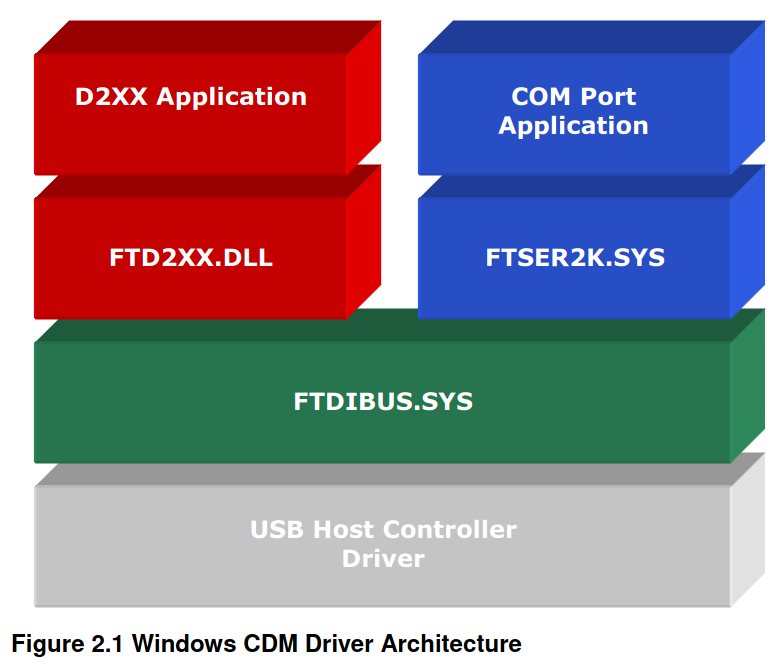
而在 类Unix平台 和 Windows CE 上,VCP 和 D2XXX 是相互排斥的选项,因为在一个特定的时间内,一个特定的设备ID只能安装一种驱动类型。
Windows 上虽然可以装 VCP 和 D2XXX 两种驱动,但是任意时间也只有一种驱动能用。
VCP 是专用于 虚拟串口 的驱动,因此FTDI 官方并不提供 应用级 示例代码。而 D2XXX 是 FTDI 的专用接口,官方提供了 FTD2XXX 库的应用程序以供开发。
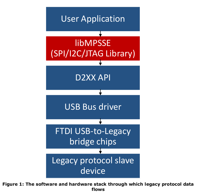
其中,libMPSSE 是 SPI/I2C/JTAG 的通信的库文件,依赖于底层的 libftd2xx

位模式的必要值。这设置了哪些位是输入和输出。位值为0时,将相应的引脚设为输入,位值为1时,将相应的引脚设为输出。
在CBUS Bit Bang的情况下,这个值的上位数控制哪些引脚是输入和输出,而下位数控制哪些输出是高电平和低电平。
注意: 它与 FT_SetBitMode() 不是互相的关系
根据 SPI PINOUT 的图标说明,应该将以下引脚的掩码设置为如下:
| 主控引脚 | 所接从设备引脚 | 输入输出状态 | 掩码 |
|---|---|---|---|
| A0 | SCLK | output | 1 |
| A1 | MOSI | output | 1 |
| A2 | MISO | input | 0 |
| A3 | SNCS | output | 1 |
| A4 | x | ||
| A5 | x | ||
| A6 | x | ||
| A7 | x |
此时,掩码必须设置为 0xFB 或 0x0B
0x0= Reset0x1= Asynchronous Bit Bang0x2= MPSSE (FT2232, FT2232H, FT4232H and FT232H devices only)0x4= Synchronous Bit Bang (FT232R, FT245R, FT2232, FT2232H, FT4232H and FT232H devices only)0x8= MCU Host Bus Emulation Mode (FT2232, FT2232H, FT4232H and FT232H devices only)0x10= Fast Opto-Isolated Serial Mode (FT2232, FT2232H, FT4232H and FT232H devices only)0x20= CBUS Bit Bang Mode (FT232R and FT232H devices only)0x40= Single Channel Synchronous 245 FIFO Mode (FT2232H and FT232H devices only)
FT_GetBitMode 返回各引脚的瞬时值。将返回一个单字节,其中包含各引脚的当前值,包括那些输入和输出的引脚。
或对FT232R的可用位模式的描述,请参见应用说明 "FT232R和FT245R的bit-bang模式"。 关于FT2232的可用位模式的描述,请参见应用说明 "FT2232的位模式功能"。 关于FT232B和FT245B的比特爆炸模式的描述,见应用说明 "FT232B/FT245B比特爆炸模式"。 关于T4232H和FT2232H器件支持的位模式的描述,请参见IC数据表。 这些应用说明可从FTDI网站下载。
数据传输的速率可以通过使用 FT_SetBaudRate()
命令来控制。异步模式的时钟实际上是所设波特率的16倍。一个9600波特的值将以每秒(9600x16)=153600
byte的速度传输数据,或每6.5μS一个 byte。
FTDI 器件最大可设置的波特率是
3M baud,但为了让数据有时间在 WR#
选通周围设置和保持,数据的波特率最大应该是
1M baud(62500x16)。最小的数据波特率是
4.8kbaud(300 x 16)。
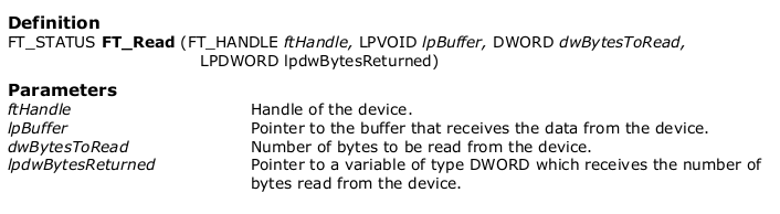
FT_Read always returns the number of bytes read in lpdwBytesReturned. This function does not return until dwBytesToRead bytes have been read into the buffer. The number of bytes in the receive queue can be determined by calling FT_GetStatus or FT_GetQueueStatus, and passed to FT_Read as dwBytesToRead so that the function reads the device and returns immediately.
When a read timeout value has been specified in a previous call to FT_SetTimeouts, FT_Read returns when the timer expires or dwBytesToRead have been read, whichever occurs first. If the timeout occurred, FT_Read reads available data into the buffer and returns FT_OK. An application should use the function return value and lpdwBytesReturned when processing the buffer. If the return value is FT_OK, and lpdwBytesReturned is equal to dwBytesToRead then FT_Read has completed normally. If the return value is FT_OK, and lpdwBytesReturned is less then dwBytesToRead then a timeout has occurred and the read has been partially completed. Note that if a timeout occurred and no data was read, the return value is still FT_OK.
FT_Read() 总是返回在 lpdwBytesReturned
中读取的字节数。 在 dwBytesToRead
字节被读入缓冲区之前,该函数不会返回。接收队列中的字节数可以通过调用FT_GetStatus()
或 FT_GetQueueStatus() 来确定,并作为
dwBytesToRead 传给
FT_Read(),以便该函数读取设备并立即返回。
当在先前对 FT_SetTimeouts()
的调用中指定了一个读取超时值时,FT_Read() 在定时器过期或
dwBytesToRead
已被读取时返回,以先发生者为准。如果超时发生,FT_Read()
将可用数据读入缓冲区并返回 FT_OK。
在处理缓冲区时,应用程序应使用该函数的返回值和
lpdwBytesReturned 。如果返回值为 FT_OK,并且
lpdwBytesReturned 等于 dwBytesToRead ,那么
FT_Read() 已经正常完成。如果返回值是
FT_OK,并且 lpdwBytesReturned 小于
dwBytesToRead,那么就发生了一个超时,读取已经部分完成。
请注意,如果发生了超时并且没有读取任何数据,返回值仍然是
FT_OK 。FT_IO_ERROR
的返回值表明函数的参数有错误,或者发生了致命的错误,如USB断开连接。
异步 Bit-Bang 模式与 BM-style Bit-Bang 模式相同。在任何配置为异步模式的通道上,以正常方式写入设备的数据将被自锁到并行I/O数据引脚(那些被配置为输出的引脚)。每个I/O引脚都可以独立设置为输入或输出。数据的时钟输出速率由波特率发生器控制。
为了使数据发生变化,必须有新的数据写入,而且 波特率时钟 必须跳动。如果没有新的数据被写入通道,引脚将保持最后写入的值。
- 那这个波特率时钟 怎么控制?能否指定任一引脚进行输出?
The synchronous Bit-Bang mode will only update the output parallel I/O port pins whenever data is sent from the USB interface to the parallel interface. When this is done, data is read from the USB Rx FIFO buffer and written out on the pins. Data can only be received from the parallel pins (to the USB Tx FIFO interface) when the parallel interface has been written to.
With Synchronous Bit-Bang mode, data will only be sent out by the FT4232H if there is space in the FT4232H USB TXFIFO for data to be read from the parallel interface pins. This Synchronous Bit-Bang mode will read the data bus parallel I/O pins first, before it transmits data from the USB RxFIFO. It is therefore 1 byte behind the output, and so to read the inputs for the byte that you have just sent, another byte must be sent.
同步模式只有在数据从USB接口发送到并行接口时才会更新输出的 并行I/O端口 引脚。当这样做的时候,数据从USB Rx FIFO缓冲器中读出,并在引脚上写出。只有当并行接口被写入时,才能从并行引脚接收数据(到USB Tx FIFO接口)。
同步Bit-Bang模式与异步Bit-Bang模式的不同之处在于,只有当USB接口写入并行输出时,设备的并行输出才被读取。这使得控制程序更容易测量对USB输出刺激的反应,因为返回到USB接口的数据与输出数据是同步的。
在同步模式下,读和写操作会被同步进行。此时,数据总线引脚会在写入数据前先读取数据(针对每个byte)。因此,该数据引脚读取到的数值总是比写出去的数值要慢一个byte。
与异步模式不同,数据引脚只会在写入数据前立即进行读取操作。因此,为了读取 “写入一个byte的响应结果” ,必须要发送另一个byte。 另外,只有当设备中有空间可以从引脚读取数据时,数据才会被写入引脚。
每个引脚都可以独立设置为输入或输出。数据的时钟输出率由波特率发生器控制。要改变引脚的状态,必须写入新的数据,并且波特率时钟必须跳动(the baud rate clock hask to tick)。如果没有新的数据被写入设备,输出引脚将保持最后写入的数值。
当同步模式被启用时,I/O信号线的配置如表3.1所示。请注意,在首次进入同步模式后,任何引脚的默认配置,如果设置为输出,则默认被设置为
输出低电平(0V)。(随后向任何引脚写一个 1
将把该引脚设置为VCCIO)
当进入同步模式后,如果希望在任何输出上驱动一个高值,那么有必要首先用
FT_SetBitMode() 方法把这些引脚设置为输入,用
FT_Write() 把它们写一个 1 ,然后用
FT_SetBitMode()
把它们设置为输出。请注意,当设备处于同步位串模式时,EEPROM
UART信号反转选项(signal inversion option)对这些引脚没有影响。
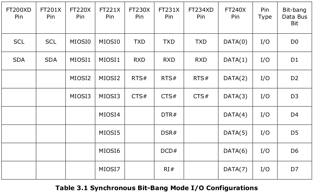
FT200XD 和 FT201X提供两条信号线;FT220X、FT230X 和 FT234XD提供四条信号线;而 FT221X、FT231X 和 FT240X上总共有八条信号线。
任何一个FT-X系列器件的CBUS引脚都可以被配置为在器件处于同步位串模式时发出
内部读取 RD# 或 内部写入
WR#
频段(strobes)(注意,FT200XD、FT220X、FT221X和FT234XD只有一个CBUS
引脚,因此只能选择 RD# 或 WR#
)。通过在内部EEPROM中设置适当的值,CBUS
引脚也可用于提供时钟信号。
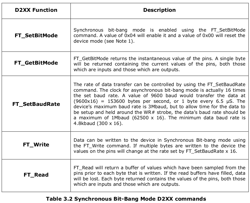
所有的bit-bang模式都需要使用D2XX驱动,不可能通过VCP驱动使用这些功能,也不可能同时使用
CBUS bit-bang 和
VCP。表3.2列出了用于同步 bit-bang
模式的基本命令。这些功能的完整描述可在《D2XX程序员指南》中找到。
FT432 如果需要配置成 Bit-Bang模式,需要:
FT_Open() 打开对应通道FT_SetBitMode() 为8个pin配置输入或输出,FTDI
称之为掩码(mask),0则代表输入,1则代表输出,例如 0x0F
则代表 0~3 pin 设置为输出,4~7
pin设置为输入。FT_SetBitMode() 第三个参数
ucEnable 传递参数即可打开对应模式,如:
FT_BITMODE_SYNC_BITBANG 即 同步 Bit-Bang 模式FT_BITMODE_SYNC_BITBANG 即 异步 Bit-Bang 模式FT_BITMODE_RESET 即 默认的 UART 模式。FT_SetBaudRate()
传递参数即可设置SPI通信频率。实际上此处设置的并不是
SPI外设的工作频率,而是该 channel 通过 FT_Write()
接口改变引脚高低电平的频率。
100000 波特率约为
250KHz 时钟,如果使其工作在 1MHz
频率下,则需要设置波特率为 400000。16 倍FT_Write() 和
FT_Read()
会按照该通道设定的时钟频率去改变/读取引脚数据。操作一次 FT_Write() ,如下,即可在 一个频率的半个周期内 改变 8个pin 的高低电平。
1 | bytes_written_number = 0; |
ft_handle 是通道的句柄(注意:一个通道一个句柄,不是一个句柄适用所有通道)
byte_write_to_slave.all 是一个 8bit 的 UCHAR 类型数据。
bits_to_send 为 待发送数据量
bytes_written_number 是 已写入数据量
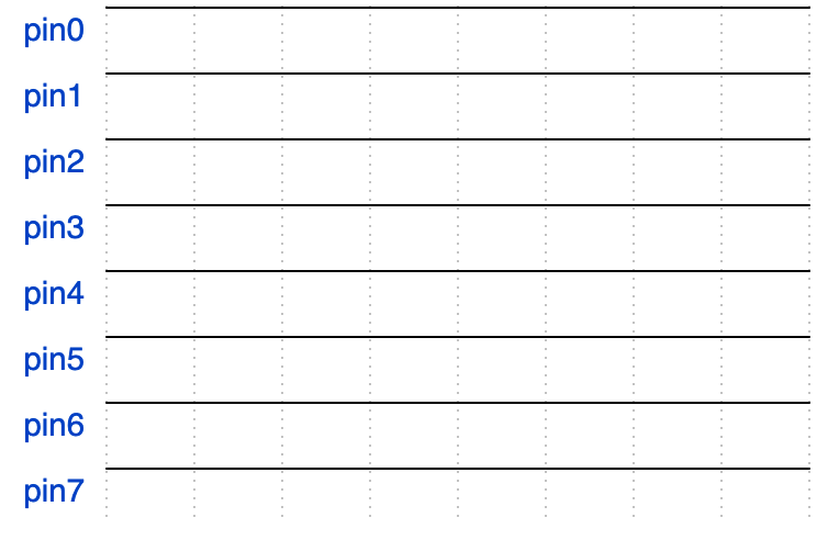
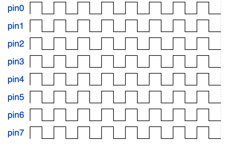
如果将 掩码 配置为 0xFF
,即8个通道均为输出。且输出每个通道单次输出的数值,均为
0xFF,输出 16次,即调用 FT_Write()
16次,那么得到的图像应该如下:
如果将 掩码 配置为 0xFF 。交替输出 0xFF 和
0x00,输出 16 次,那么得到的图像应该如下:
Q: 为什么上面只有8个时钟,即1个byte大小,为什么是输出16次?
A: 因为FTDI的 FT_Write()
接口写入一次数据,只能控制半个周期内的8个pin脚数据,如果需要发送一个周期的数据,则需要写两次,如果需要发送8个bit,则需要输出16次。
如果将 掩码 配置为 0x0B,即 0000 1011
,(按照 MPSSE-SPI Example 设置的相同配置),pin0 为
SCK ,pin1 为 MOSI,
pin2 为 MISO , pin3 为
CS 。
默认情况下,输入引脚的电平会被拉低。如果设置为输入引脚,FT_Write()
无法改变其电平。
FT_Write() 一共需要写入 32次数据:
1 | UCHAR byte_write_to_slave[32] = { |
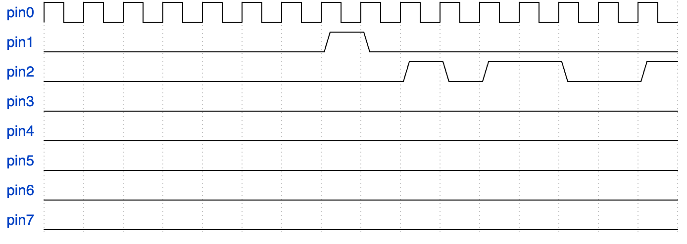
可以看到在 byte_write_to_slave[14] 和
byte_write_to_slave[15] 时需要主动拉高 pin1
的电平,并维持 2个 falf period(即 one period)。
再用 FT_Read() 读取 32 次数据,将数据存储到
UCHAR byte_read_from_slave[32] 中,并从
byte_read_from_slave[16] ~
byte_read_from_slave[31] 的 16
个数据中,每间隔1个数据,将对应 pin2 的数据左移存储到
data_read 中。
代码可以是这样的:
1 | UCHAR data_read = 0; |
Q: 为什么 FT_Read()
需要读取32次数据?
A: 因为这是 同步 Bit-Bang 模式的特性,根据手册说明,每次读取一定数据量之前,都要写入一定的数据量。异步 Big-Bang 模式是不用这样的。
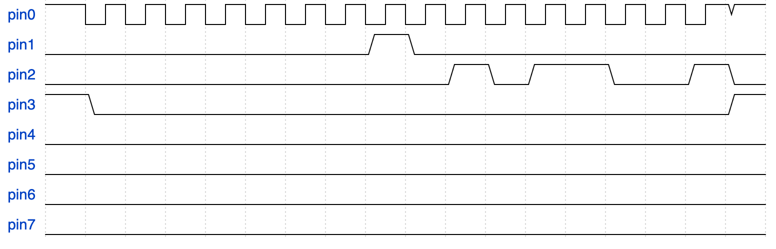
如果按照例3 的方法去发送数据,可能会发现收到的数据一直是异常的。
因为 输出引脚 会保持其最后的输出电平,如 byte_read_from_slave[31] 数据为 0x00,这就让 pin0 ,即 SCK 发送完数据之后保持了低电平,与 CPOL=1 的要求相违背。
因此不能只发送和接收32个数据,而应该在对应的发送数据的前后加上一个周期,即声明一个长度为36的数组 UCHAR byte_read_from_slave[36] 。
byte_read_from_slave[0] /
byte_read_from_slave[1] /
byte_read_from_slave[34] /
byte_read_from_slave[35] 均应设置为 0x09
,如下波形所示。
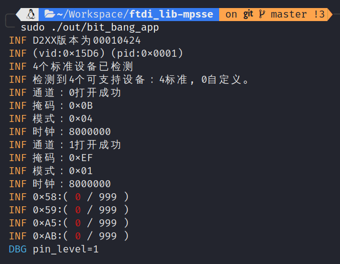
FTDI HAL 是基于 D2XX 库、由个人编写的、可替换libMPSSE的SPI库,目前仅有SPI相关的代码。
各通道的可以配置不同的handle和config 参数去打开和关闭。也可以读GPIO,没问题了。
1 | /** |
350ns ,周期约为
750ns ),发送 10000次后停止,该接口能够读取到
76~80 次。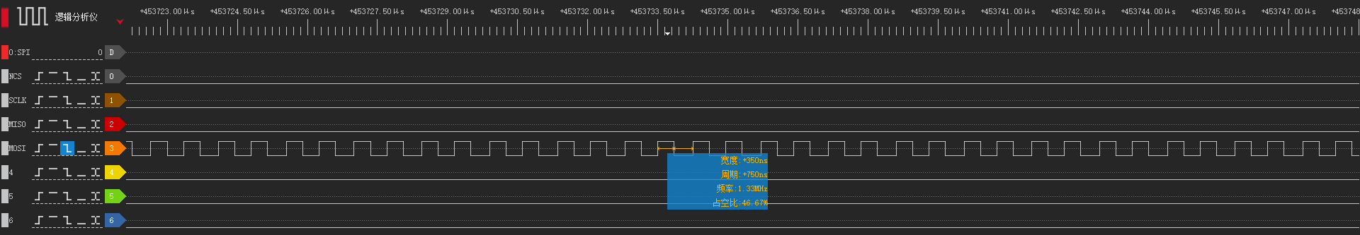
33us,同样发送
10000次后停止,该接口能够读取到 6660
次左右。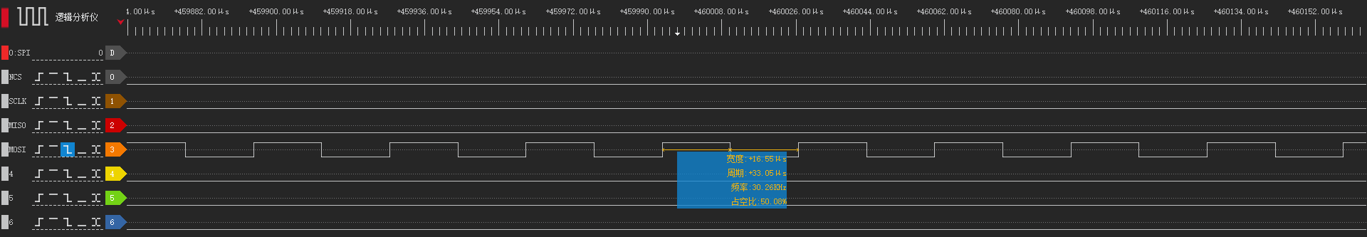

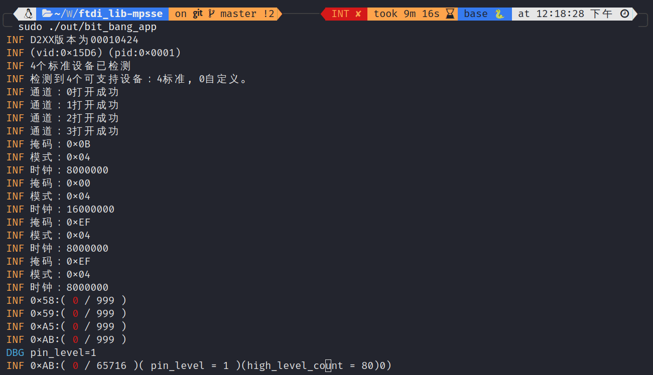
GPIO电平读取频率大致在 5KHz ~ 50KHz
之间,即接口两次调用的时间间隔在 20us ~ 200us
之间。
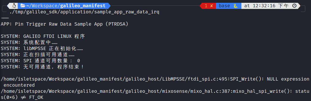
这是因为运行需要 sudo 权限,即
sudo ./tmp/galileo_sdk/application/sample_app_raw_data_irq
。如果还是不行,应该是没有卸载 ftdi_sio 和
usbserial ,即 sudo rmmod ftdi_sio usbserial
。
注意:卸载 usbserial
后,如果这时候linux系统内有其他设备对 libusb-1.0-0-dev
有依赖,那它会无法正常工作。
"D:\STMicroelectronics\STM32Cube\STM32CubeProgrammer\bin\STM32_Programmer_CLI.exe",这种方法可以在
PowerShell 或 cmd 直接使用。"D:\STMicroelectronics\STM32Cube\STM32CubeProgrammer\bin
添加到 系统环境变量 中,这种方法只有 PowerShell
可以使用,cmd 还是不可以。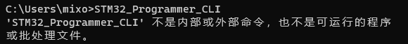
STM32_Programmer_CLI 的指令参数有多种分类,包括适用于 STM32 MCU 、STM32 MPU、MCU安全烧录、STM32WBxx 三个部分。
下面是这个软件的官方说明:
1 | ------------------------------------------------------------------- |
下面语句可以查看所有连接至PC端的设备。
1 | STM32_Programmer_CLI -l |
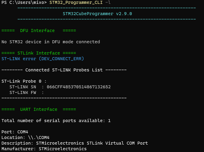
详见:
1 | -l, --list : List all available communication interfaces |
可以使用多种连接方式,将ST的从设备与PC上位机进行连接,包括 USB / UART / JTAG / SWD / SPI / CAN / I2C 。
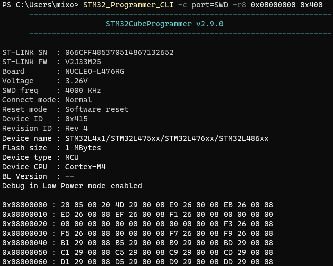
使用指令 STM32_Programmer_CLI -c port=SWD
即可自动连接至设备。

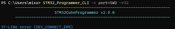
使用指令
STM32_Programmer_CLI -c port=SWD -r32 0x08000000 0x400
可以从 地址 0x08000000 起,以 32bit
格式(-r32 )读取 0x400 byte
数据。
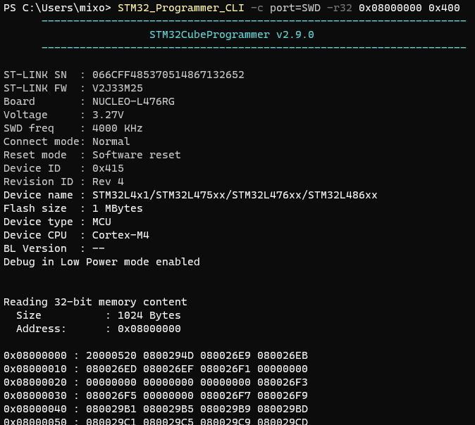
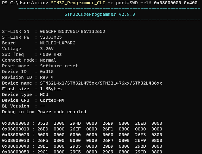
-r32 可以更换成 -r16 或 -r8
。
大面积擦除(Mass erase)所有内容,一般来说烧录的时候不会去擦除全部内容,这部分应该看情况。
1 | STM32_Programmer_CLI -c port=SWD -e all |
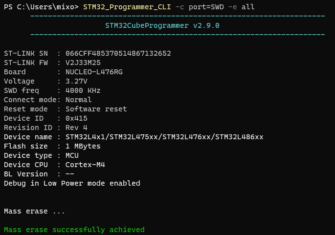
详见:
1 | -e, --erase : Erase memory pages/sectors devices: |
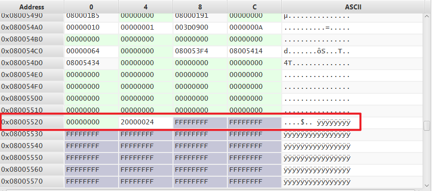
下面两张图是烧录完某 .bin
文件后,flash内部结束尾部临界处的数据。交替烧录两个大小不易的
.bin 文件,可以观察到结尾处都是正常的,并没有出现异常。
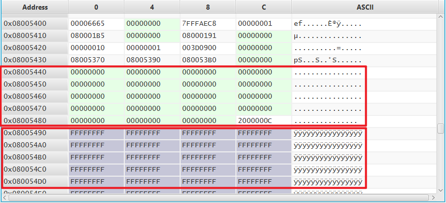
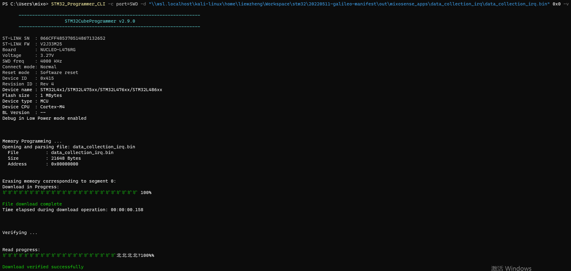
1 | STM32_Programmer_CLI -c port=SWD -d "\\wsl.localhost\kali-linux\home\liewzheng\Workspace\stm32\20220511-galileo-manifest\out\mixosense_apps\data_collection_irq\data_collection_irq.bin" 0x00 -v |
-d 是指 文件下载,后方接 文件路径
以及 起始地址 0x00 。这个起始地址应该是
0x08000000 还是 0x00 我也还没搞清楚。
-v 是指 代码验证。
详见:
1 | -d, --download : Download the content of a file into device memory |
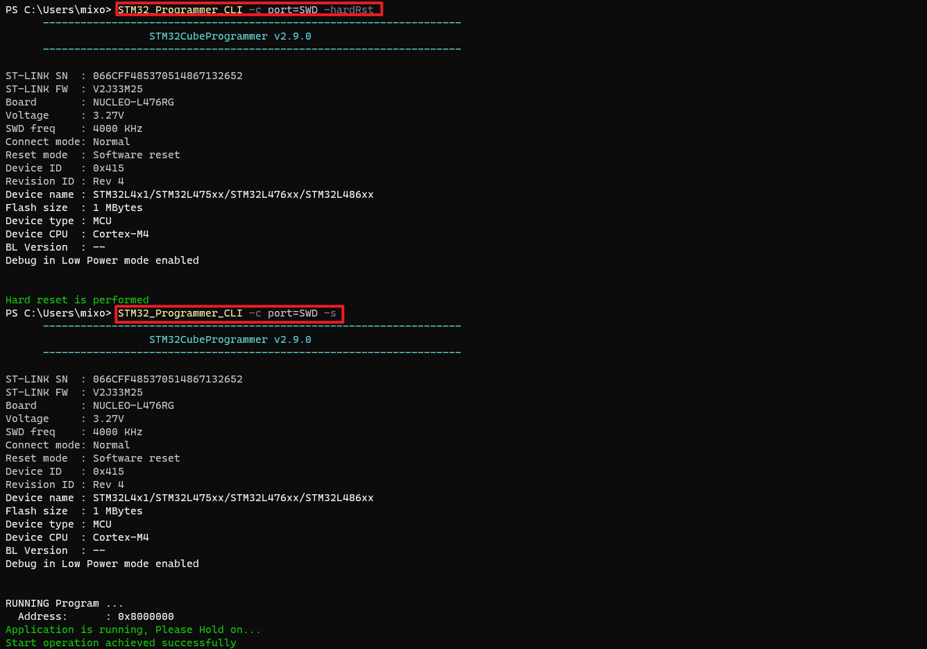
1 | STM32_Programmer_CLI -c port=SWD -hardRst |
下面所有的脚本都会类比 Linux Shell Script 进行。
Windows有两个命令行 shell:Command shell 和 PowerShell。 每个 shell 都是一个软件程序,它提供你与操作系统或应用程序之间的直接通信,提供一个环境来自动执行 IT 操作。
Command shell 是内置于 Windows中,用于自动执行常规任务(例如用户帐户管理或夜间备份)和批处理 (.bat) 文件。 使用Windows脚本主机,可以在命令外壳中运行更复杂的脚本。 有关详细信息,请参阅 cscript 或 wscript。 通过使用脚本可以比使用用户界面更有效地执行操作。 脚本接受命令行中提供的所有命令。
PowerShell 旨在扩展 Command shell 的功能,以运行名为 cmdlet 的 PowerShell 命令。 Cmdlet 类似于 Windows命令,但提供了更具可扩展性的脚本语言。 可以在 PowerShell 中Windows命令和 PowerShell cmdlet,但命令外壳只能运行 Windows 命令,不能运行 PowerShell cmdlet。
若要实现最可靠、最新的自动化Windows,建议使用 PowerShell 而不是 Windows 命令或 Windows 脚本主机Windows自动化。
windows bat 批处理和 PowerShell 都可以使用 ::
作为注释头部信息。与 Linux Shell Script 和 Python 的 #
不一致(反人类罪)。
1 | :: 注释 |
del 删除命令只能删除文件,rd
可以删除文件夹
/Q 是静默删除,不提示文字。/S
除目录本身外,还将删除指定目录下的所有子目录和文件。用于删除目录树。
1 | :: 静默删除所有文件和文件夹 |
| Windows Bat | Windows PowerShell | Linux Shell | Others |
|---|---|---|---|
| help | Get-Help | man | |
| cd /D | Set-Location | cd | |
| cd | Get-Location | pwd | |
| type | Get-Content | cat | |
| rd /S rmdir /S |
Remove-Item | rm -r | |
| del erase |
Remove-Item | rm | |
| dir /b | ls | ||
| dir | Get-ChildItem | ll | |
| cls | Clear-Host | clear | |
| doskey | Set-Alias | alias | |
| md mkdir |
New-Item | mkdir | |
| move | Move-Item | mv | |
| ren rename |
Rename-Item | mv | |
| copy | Copy-Item | cp | |
| echo | Write-Output | echo |
bat 的条件语句教程:《if》
PowerShell 的条件语句教程:《about_If》