TI多核开发
多核开发涉及多核通信及任务分配管理的问题,任何多核通信都需要针对具体芯片的型号及系统特性去设计。多核通信包括资源共享、竞争、同步、异步等问题;多核任务分配则关系着各核心任务均衡和RTOS系统能否及时响应的问题。
1. 基础知识
并发、并行、异步、同步、共享、互斥、进程、线程
Concurrency 并发
仅表示计算机可以同时执行多项任务,以至于如何实现“同时”执行,则有许多不同形式。
如,单核处理器可以通过分配时间片,轮询任务来达到多任务并发。系统让一个任务运行一段时间,在切换到另一个任务运行,如此循环往复,此过程也被称为 线程的上下文切换(Context Switching)。
Parallelism 并行
多个任务于同一时刻在不同的和核心上进行处理,称为并行
Synchronization 同步
指程序任务间的先后关系,后面一个程序必须等前一个任务执行完毕方可启动。因此,在同步中,并无并发或并行概念
Asynchronization 异步
指不同的任务之间不会相互等待
对于I/O资源访问频繁的系统,宜使用异步编程,
Mutual Exclusion 互斥
程序内存开销 及 线程切换开销
堆、栈
题目所指的 heap 和 stack 在 C++
标准中相对的术语分别是自由存储(free
store,即用new创建对象时所分配的空间)和自动变量(automatic
variable,或称为局部变量,不要与 C++11 的auto混淆)。
编程角度,要分开两者,是因为两者的生命周期不一样。
如果只需要在作用域内维持变量的生命周期,最好就用自动变量,这样是最简单方便高效的。其他情况可考虑用自由存储、静态局部/全局变量,或类的(静态)成员变量。它们各有不同特点,不在此答案详述。另外,由于 C++ 不支持可变长数组(VLA),不可以定义动态长度的自动变量(成员变量也不行),这个情况下也需要用 new[] 来创建动态长度的数组。
自动变量会在作用域(如函数作用域、块作用域等)结束后析构、释放内存。因为分配和释放的次序是刚好完全相反的,所以可用到堆栈先进后出(first-in-last-out, FILO)的特性,而 C++ 语言的实现一般也会使用到调用堆栈(call stack)来分配自动变量(但非标准的要求)。 自由存储可以在函数结束后继续生存,所以也需要配合 delete 来手动析构、释放内存(也可使用智能指针避免手动 delete)。由于分配和释放次序没有限制,不能使用堆栈这种数据结构做分配,实现上可能采用自由链表(free list)或其他动态内存分配机制。
堆,英文是 heap,在内存管理的语境下,指的是动态分配内存的区域。这个堆跟数据结构里的堆不是一回事。这里的内存,被分配之后需要手工释放,否则,就会造成内存泄漏。
C++ 标准里一个相关概念是自由存储区(free store),特指使用
new 和 delete
来分配和释放内存的区域。一般而言,free
store是堆(heap)的一个子集,原因如下:
new和delete操作的区域是 free store;malloc和free操作的区域是 heapnew和delete通常底层使用malloc和free来实现
栈,英文是 stack,在内存管理的语境下,指的是函数调用过程中产生的本地变量和调用数据的区域。这个栈和数据结构里的栈高度相似,都满足“后进先出”(last-in-first-out 或 LIFO)。
RAII,完整的英文是 Resource Acquisition Is Initialization,是 C++ 所特有的资源管理方式。有少量其他语言,如 D、Ada 和 Rust 也采纳了 RAII,但主流的编程语言中, C++ 是唯一一个依赖 RAII 来做资源管理的。
RAII 依托栈和析构函数,来对所有的资源——包括堆内存在内——进行管理。对 RAII 的使用,使得 C++ 不需要类似于 Java 那样的垃圾收集方法,也能有效地对内存进行管理。RAII 的存在,也是垃圾收集虽然理论上可以在 C++ 使用,但从来没有真正流行过的主要原因。
嵌入式的设备如DSP上的栈空间是Kb级别,在函数内定义数组或申请空间都不能像linux下那样直接定义和申请,要么定义成全局的,要么指向一块划分好的空间,否则就会造成覆盖代码段等的问题。
DSP的所有变量,函数,以及程序员定义的地址都保存在这三片空间上,程序员在定义变量时,若没有特殊规定,则编译器自动把变量分配到可读写空间上的任意位置,所以当程序员使用
int *p = 0x00810000
;这种语法的时候,很有可能会覆盖掉程序保存变量和函数的空间,导致程序运行异常,因此需要一个
.cmd
文件来约束,哪些地方用来给程序员自己定义变量地址用,哪些地方用来给程序为变量和函数申请内存来用。
2. 多核通信模块
IPC Modules can be used in a variety of combinations.
以上即是说,各类IPC模块可以根据需要进行组合混用。
IPC以独立插件的形式进行安装与使用,使用时可能需要手动挂载至项目属性中。
Here are some introductions about heap in the <SPRUEX3K.pdf> as follows:
SYS/BIOS provides the following Heap implementations: - HeapMem. Allocate variable-size blocks. Section 6.8.1 - HeapBuf. Allocate fixed-size blocks. Section 6.8.2 - HeapMultiBuf. Specify variable-size allocation, but internally allocate from a variety of fixed-size blocks. Section 6.8.3
| Module | Module Path | |
|---|---|---|
| GateMP(门) | GateMP |
Manages gates for mutual exclusion of shared resources by multiple
processors and threads. See Section 2.6. |
| HeapBufMP(堆缓存) | ti.sdo.ipc.heaps.HeapBufMP |
Fixed-sized shared memory Heaps. Similar to SYS/BIOS’s
ti.sysbios.heaps.HeapBuf module, but with some
configuration differences. See Section 2.5. |
| HeapMemMP(堆储存) | ti.sdo.ipc.heaps.HeapMemMP |
Variable-sized shared memory Heaps. See Section 2.5. |
| HeapMultiBufMP(堆混合缓存) | ti.sdo.ipc.heaps.HeapMultiBufMP |
Multiple fixed-sized shared memory Heaps. See Section 2.5. |
| Ipc(核间通信) | ti.sdo.ipc.Ipc |
Provides Ipc_start() function and allows startup
sequence configuration. See Section 2.2. |
| ListMP(列表) | ti.sdo.ipc.ListMP |
Doubly-linked list for shared-memory, multi-processor applications.
Very similar to the ti.sdo.utils.List module. See Section 2.4. |
| MessageQ (Q报文) | ti.sdo.ipc.MessageQ |
Variable size messaging module.
可拥有不同大小的信息模块。 See Section 2.3. |
| TransportShm(运输表) | ti.sdo.ipc.transports.TransportShm |
Transport used by MessageQ for remote communication with other
processors via shared memory. See Section 2.3.11. |
| Notify (通知) | ti.sdo.ipc.Notify |
Low-level interrupt mux/demuxer module. See Section 2.7. |
| NotifyDriverShm(通知驱动表) | ti.sdo.ipc.notifyDrivers.NotifyDriverShm |
Shared memory notification driver used by the Notify module to
communicate between a pair of processors. See Section 2.7. |
| SharedRegion (共享区域) | ti.sdo.ipc.SharedRegion |
Maintains shared memory for multiple shared regions. See Section 2.8. |
Header Files included
除了<ipc_install_dir>/packages/ti/ipc/
路径下可以找到IPC必须的头文件外,
<ipc_install_dir>/packages/ti/sdo/ipc/
路径下同样有IPC的头文件,但是请勿直接引用至 .c文件中。
1 |
|
Standard IPC Function Call Sequence
Standard IPC Function Call Sequence,即标准IPC函数的调用顺序。
MODULE 在本处指任一类型的IPC调用(如,GateMP、IPC、MessageQ等),如
MODULE_Open()即可替换成MessageQ_Open(),具体实参见对应的头文件。
An application that uses IPC APIs—such as MessageQ,
GateMP, and ListMP—must include the
Ipc module header file and call Ipc_start() in the
main() function. Ipc_start() does
the following:
- 初始化:Initializes a number of objects and modules used by IPC.
- 同步:Synchronizes multiple processors so they can boot in any order.
NOTES: If the main() function calls any
IPC APIs, the call to Ipc_start() must be placed before any
calls to IPC modules.
调用顺序
- Firstly, initialize a
MODULE_Paramsstructure to its default values via aMODULE_Params_init()function. The creator thread can then set individual parameter fields in this structure as needed. - Secondly, calls the
MODULE_create()function to creates the instance and initializes any shared memory used by the instance. If the instance is to be opened remotely, a unique name must be supplied in the parameters. - Other threads can access this instance via the
MODULE_open()function, which returns a handle with access to the instance. The name that was used for instance creation must be used in theMODULE_open()function. - Finally, the thread that called
MODULE_create()can callMODULE_delete()to free the memory used by the instance.
- 首先,使用
MODULE_Params_init()来初始化MODULE_Params结构。(创建它的线程)可以根据需要单独调整结构体内的个别参数。- 然后,调用
MODULE_create()函数来创建对象实例,并初始化其内存。如果该对象在别处被打开,需要给被调用的参数取好名字防止重复。- 接着, 其他线程可以通过
MODULE_open()函数接入该对象,并返回一个对应的句柄。该对象的创建名称必须与打开名称保持一致。- 最后,调用
MODULE_create()来创建对象实例的线程就可以调用MODULE_delete()来释放被对象占用的内存。
注意:
All threads that opened an instance must close that instance before the thread that created it can delete it. Also, a thread that calls
MODULE_create()cannot callMODULE_close(). Likewise, a thread that callsMODULE_open()cannot callMODULE_delete().在由创建者删除(delete)某IPC对象时,由谁使用(open)就由谁关闭(close)。且决不能由创建者来调用关闭函数,否则创建者无法删除该对象。(顺序如下图所示)
stateDiagram-v2
    [*] --> Core0
    [*] --> Core1
    Core0 --> IPC_Start()
    IPC_Start() --> Module_Create()
    IPC_Start() --> Core1 : Wait for Sychronization
    Core1 --> UsersProgram()
    UsersProgram() --> Module_Open()
    Module_Open() --> Module_Close()
    Module_Create() --> Module_Delete()
    Module_Close() --> Module_Delete() : Closed by who opens
代码示例
Ipc_Start() 使用示例
1 |
|
MessageQ_Create() 使用示例
1 | messageQ = MessageQ_create(DSP_MESSAGEQNAME, NULL); |
Error Handling in IPC
Success codes always have values greater or equal to zero. The Failure codes are always negative.
1 | MessageQ_Msg msg; |
IPC Module Configuration
Configure how the IPC module synchronizes processors by configuring
the Ipc.procSync property. For example:
1 | /* CONFIGURATION ABOUT INTER-PROCESS COMMUNICATION */ |
Here are three options: Ipc.ProcSync_ALL |
Ipc.ProcSync_PAIR | Ipc.ProcSync_NONE
| Options | Conditions | Specialties |
|---|---|---|
| Ipc.ProcSync_ALL | - IPC processors on a device start up at the same time - Connections should be established between every possible pair of processors |
- Ipc_start() API automatically attaches to and
synchronizes all remote processors. - Application should never call Ipc_attach(). |
| Ipc.ProcSync_PAIR (Default Mode) | One of the following is true: - You need to control when synchronization with each remote processor occurs. - Useful work can be done while trying to synchronize with a remote processor by yielding a thread after each attempt to Ipc_attach() to the processor. - Connections to some remote processors are unnecessary and should be made selectively to save memory. |
- Must explicitly call Ipc_attach() to attach to a
specific remote processor. - Ipc_start() performs
system-wide IPC initialization, but does not make connections to
remote processors. |
| Ipc.ProcSync_NONE | Use this option with caution. It is intended for use in cases where the application performs its own synchronization and you want to avoid a potential deadlock situation with the IPC synchronization. |
Ipc_start() doesn’t synchronize any processors before
setting up the objects needed by other modules. |
Attach and Detach (依附与分离)
In addition to the default actions performed when attaching to or detaching from a remote processor, You can configure a function to perform custom actions.
Attach and Detach are provided for the processor synchronization:
Ipc_attach()Creates a connection to the specified remote processor.Ipc_detach()Deletes the connection to the specified remote processor.
在 .cfg
文件中以下为两个互相依赖和两个互相分离的函数配置,每一组函数都会传递一个不同的参数:
1 | var Ipc = xdc.useModule('ti.sdo.ipc.Ipc'); |
These functions run near the end of
Ipc_attach() and near the beginning of
Ipc_detach() , respectively.
Such functions must be non-blocking and must run to completion. 这些被定义的函数必须为非阻塞且(一旦开始就)运行到底。
注意: Call Ipc_attach() to the
processor that owns shared memory region 0 (usually the processor with
id = 0) before making a connection to any other remote processor. For
example, if there are three processors configured with
MultiProc, #1 should attach to #0 before it
can attach to #2.
3. 多核任务分配
如果多个核共享一个工程及相同的bios 配置文件,是不能指定某一个任务到特定的core上,如果某个任务只有某个core才会运行,可以在任务中区分core运行。如果多个core分别有不同的工程,则没有“多核任务分配”的问题,每个工程可以根据各自core的应用创建各自的任务,不需要软件区分core。
单核可以是一个out生成最终的bin文件烧写在flash,多核如果存在多个out文件,可以把out文件合并成一个bin烧写,或者多个bin分开烧写均可。bin文件中都有程序的地址及长度信息,在多个bin时,也是一样可以由core0负责对flash的程序文件解析,将程序搬移到相应的地址上,最后core0再向其他core magic address写入入口地址,并发送ipc触发即可。
这个并非由SYS/BIOS分配,需要开发者指定。
可以根据core number来做判断,然后确认该任务是否运行在该核上。
4. Chip Support Library
CSL,即芯片支持库( Chip Support Library)。在程序设计过程中利用CSL库函数可以方便地访问 DSP的寄存器和硬件资源,提高DSP软件的开发效率和速度。
CSL库包含了对INTC、Boot Configuration、BWMNGMT、CACHE、CHIP、CPINTC、EDMA3、EMAC、EMIF4F、GPIO、IDMA、IPC、MDIO、MEMPROT、MPU、MSMC、PLLC、PSC、Semaphore、SGMII、SRIO、TIMER、TSC、VCP2、XMC、CGEM、CPPI、QMSS、CPPI_LLD_SYMBOL 及 CPPI_LLD_ENUM共30种模块的支持。
Cache Module
位于 ti\pdk_C6657_1_1_2_6\packages\ti\csl\ 下的头文件
<csl_cacheAux.h>
提供了缓存(Cache)配置相关的CSL功能层API。
This is the CACHE Auxilary Header File which exposes the various CSL Functional Layer API's to configure the CACHE Module.
Cache API包含了对L1D(L1 Data Cache)、L1P 及 L2的各种操作。关于L1D、L1P及L2 的详细文件参考《SPRS814D》第193页。
该头文件中对三种缓存的可操作方式如下示:
| OPERATION | L1D | L1P | L2 |
|---|---|---|---|
| setSize | √ | √ | √ |
| getSize | √ | √ | √ |
| freeze | √ | √ | √ |
| unfreeze | √ | √ | √ |
| getPrevMode -- get the previous operating state |
√ | √ | |
| invAllWait -- wait for the cache global invalidate operation to complete |
√ | √ | |
| invAll -- globally invalidate cache |
√ | √ | |
| wbAllWait -- wait for the cache writeback operation to complete |
√ | ||
| wbAll -- writeback the dirty lines of the cache |
√ | ||
| wbInvAllWait -- wait for the cache writeback invalidate operation to complete |
√ | ||
| wbInvAll -- invalidate and writeback the dirty lines of the cache |
√ | ||
| invWait -- wait for the cache invalidate block operation to complete |
√ | √ | |
| inv -- to invalidate a block in cache |
√ | √ | |
| wbWait -- wait for the cache writeback block operation to complete |
√ | ||
| wb -- writeback the dirty lines of the block address |
√ | ||
| wbInvWait -- wait for the cache invalidate/writeback block operation to complete |
√ | ||
| wbInv -- invalidate and writeback the dirty lines of the block address |
√ |
IPC Module
IPC,即进程间通信(Inter-process communication)。
位于 ti\pdk_C6657_1_1_2_6\packages\ti\csl\ 下的头文件
<csl_ipcAux.h> 提供了查询定义 和
控制函数。IPC API包含了对
NMI、GEM、Host的各种操作。其中 GEM 对 IPCGRx 及 IPCARx
进行操作;而 Host 对 IPCGRH 及 IPCARH 进行操作。
注意: 下文中, index 和
srcId
均是函数形参,如在CSL_IPC_isGEMInterruptAckSet(uint32 index, uint32 srcId)中:index
指需要检查IPCARx寄存器的GEM编号。srcId
指示在指定的索引对应的IPCARx寄存器中需要读取0-27 SRCCx位中的哪一个。
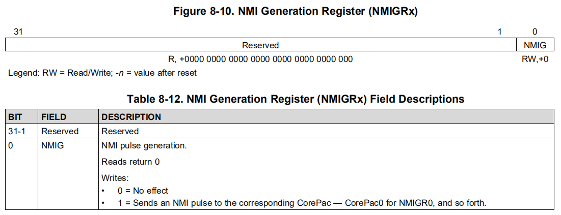
NMI,即 不可屏蔽中断(Non Maskable Interrupt)。NMIG,即 不可屏蔽中断产生寄存器(NMI Generation Register (NMIGRx))。NMIGRx registers are used for generating NMI events to the corresponding CorePac. The C6657 has two NMIGRx registers (NMIGR0 and NMIGR1). The NMIGR0 register generates an NMI event to CorePac0, and the NMIGR1 register generates an NMI event to CorePac1.Writing 1 to the NMIG field generates an NMI pulse. Writing 0 has no effect and reads return 0 and have no other effect.
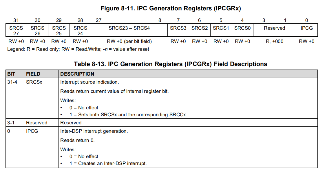
IPCGRx,即 进程间通信产生寄存器(IPC interrupt generation register)。IPCGRx are to facilitate inter CorePac interrupts. The C6657 has two IPCGRx registers (IPCGR0 and IPCGR1). These registers can be used by external hosts or CorePacs to generate interrupts to other CorePacs. A write of 1to the IPCG field of the IPCGRx register will generate an interrupt pulse to CorePacx (0 <= x <= 1).
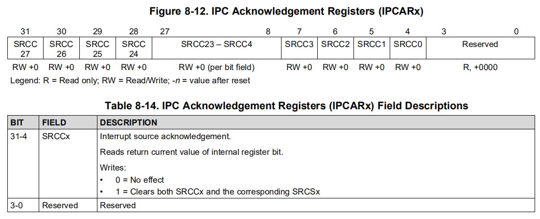
IPCARx,即 IPC中断确认寄存器(IPC interrupt-acknowledgement registers)。IPCARx are to facilitate inter-CorePac core interrupts. The C6657 has two IPCARx registers (IPCAR0 and IPCAR1). These registers also provide a Source ID facility by which up to 28 different sources of interrupts can be identified. Allocation of source bits to source processor and meaning is entirely based on software convention. The register field descriptions are shown in the following tables. Virtually anything can be a source for these registers as this is completely controlled by software. Any master that has access to BOOTCFG module space can write to these registers.
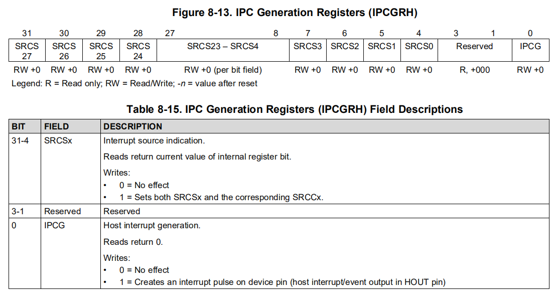
IPCGRH,即 主机IPC产生寄存器(IPC Generation Host)。The IPCGRH register facilitates interrupts to external hosts. Operation and use of the IPCGRH register is the same as for other IPCGR registers. The interrupt output pulse created by the IPCGRH register appears on device pin HOUT. The host interrupt output pulse should be stretched. It should be asserted for 4 bootcfg clock cycles (CPU/6) followed by a deassertion of 4 bootcfg clock cycles. Generating the pulse will result in 8 CPU/6 cycle pulse blocking window. Write to IPCGRH with IPCG bit (bit 0) set will only generate a pulse if they are beyond 8 CPU/6 cycle period.
IPCARH,即 主机IPC确认寄存器(Host IPC Acknowledgment Register)。
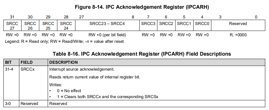
该头文件中的可操作方式如下示:
| NMI | GEM | Host | |
|---|---|---|---|
| genEvent | √ | ||
| genInterrupt -- generate an interrupt pulse |
√ | √ | |
| isInterruptSourceSet | √ -- checks if the SRCSx bit of the IPCGRx register is set |
√ -- checks if the SRCSx bit of the IPCGRH register is set |
|
| isInterruptAckSet | √ -- checks if the SRCCx bit of the IPCARx register is set. |
√ -- checks if the SRCCx bit of the IPCARH register is set. |
|
| clearInterruptSource | √ | √ |
isGEMInterruptSourceSet() returns 1 if the SRCCx bit
corresponding to the srcId is set in the IPCARx
register corresponding to the index specified.
如果与srcId对应的SRCCx位在与指定索引对应的IPCARx寄存器中被设置,则返回1。
CSL_IPC_clearGEMInterruptSource()clears the interrupt source IDs by setting the SRCCx bit of IPCARx and SRCSx bit of IPCGRx corresponding to the GEM index and Source ID specified.
CSL_IPC_clearGEMInterruptSource()通过设置 GEM 索引 和 指定源 ID 对应的 IPCARx寄存器上的SRCCx位 和 IPCGRx寄存器上的SRCSx位 来清除 中断源ID 。
CSL_IPC_clearHostInterruptSource()function clears the interrupt source IDs by setting the SRCCx bit of IPCARH and SRCSx bit of IPCGRH corresponding to the Source ID specified.
CSL_IPC_clearHostInterruptSource()通过设置 指定源ID 对应的 IPCARH上的SRCCx位 和 IPCGRH上的SRCSx位 来清楚中断源ID。
CACHE_wbInvL1d()
This function is used to invalidate and writeback the dirty lines of the block address.
Although the block size can be specified in the number of bytes, the cache controller operates on whole cache lines.
To prevent unintended behavior "blockPtr" should be aligned on the cache line size and "byteCnt" should be a multiple of the cache line size.
CACHE_invL1d ()
This function is used to invalidate a block in the L1D Cache.
Although the block size can be specified in the number of bytes, the cache controller operates on whole cache lines.
To prevent unintended behavior "blockPtr" should be aligned on the cache line size and "byteCnt" should be a multiple of the cache line size.
Chip Module
#include <csl_chipAux.h>
本头文件是以C( extern "C"
)的方式来书写的,包含芯片读取与写入相关操作的API,名称以
CSL_chipRead 或 CSL_chipWrite
开头,所有函数均以静态内联(static inline,重定义成
CSL_IDEF_INLINE )32位非负整数(Uint32)的方式定义,如
CSL_IDEF_INLINE Uint32 CSL_chipRead***(); 。
<csl_chipAux.h>
提供了26个读取寄存器相关的函数,函数定义均是对寄存器的读取并返回数值,某些读取函数需要注意
前置条件(Pre-condition)。
1 | CSL_chipReadAMR(); //Addressing Mode control register 寻址模式控制寄存器 |
<csl_chipAux.h>
提供了24个写入寄存器相关的函数,且与读取寄存器相关函数并不呈现一一对应关系。函数定义均是将一个Uint32类型(重定义为
CSL_Reg32
)的新值赋值给寄存器,并将旧值返回,写入寄存器均不需要注意
前置条件,部分需要注意后置条件(Post-condition)。
1 | CSL_chipWriteAMR(CSL_Reg32 val); |
共30个寄存器涉及是否可读写:
| Register | Read | Write |
|---|---|---|
| AMR | √ | √ |
| CSR | √ | √ |
| IFR | √ | × |
| ISR | × | √ |
| ICR | × | √ |
| IER | √ | √ |
| ISTP | √ | √ |
| IRP | √ | √ |
| NRP | √ | √ |
| ERP | √ | √ |
| TSCL | √ | √ |
| TSCH | √ | × |
| ARP | √ | √ |
| ILC | √ | √ |
| RILC | √ | √ |
| REP | √ | √ |
| PCE1 | √ | × |
| DNUM | √ | × |
| SSR | √ | √ |
| GPLYA | √ | √ |
| GPLYB | √ | √ |
| GFPGFR | √ | √ |
| DIER | √ | √ |
| TSR | √ | √ |
| ITSR | √ | √ |
| NTSR | √ | √ |
| ECR | × | √ |
| EFR | √ | × |
| IERR | √ | √ |
IPC_HW Example in ANC
硬件(中断)层核间通信(不需要修改)
1 | void Ipc_Init(void) |
核心同步(不需要修改)
1 | void Ipc_CoreSync(void){ |
核间IPC信号发送(可根据需要进行修改)
可定义多个IPC核间通信函数,但是要区分得清各函数在何时何处被调用到,否则将会引起混乱。
1 | void Ipc_Core0ToCore1(void){ |
核间通信中断函数(可根据需要进行修改)
注意:实际使用时,并不需要在某处调用
IpcIsr() 函数,即实际上是被硬件中断进行控制的,在
HWI_Create() 函数中被使用到。
1 | void IpcIsr(UArg arg){ |
5. C6657特性
L2缓存
Debug模式下,程序文件都写在L2缓存中。而C6657总共有
2048KB 大小的L2 缓存,其中每个核心分配到
1024KB ,缓存起始地址为 0x00800000 。
在仿真器中分配内存大小一致,如下:
1 | MEMORY |
Written in <TMS320C6655/57 DataManual>: